Hello
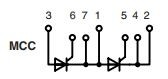
I have an old dual thyristor module like the one in the picture, it's been sitting in our workshop for ages and now I need to use it.

So i used a DMM to test it, connected the red lead to anode (3), black lead to cathode AK2 (1) and shorted the gate terminal (8) to anode, before shorting, DMM was reading about 700kohm and after shorting it was about 12ohm, so I suppose the scr turned on just fine. But when I remove the short, the scr turns off immediately, shouldn't it stay on until the current passing through it is removed? Repeated this for both thyristors in the module with the same results.
then, I used the circuit shown here to test the module again.
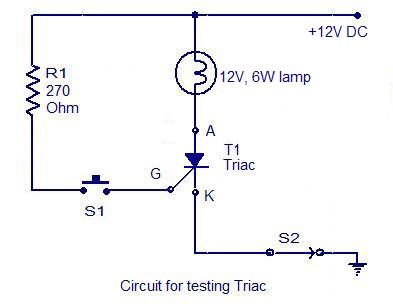
I connected anode A to terminal (3), K to terminal (1) and gate to terminal (8). However, neither thyristors in the module turned on. Although a voltage of 1v was present between G and ground (K) and a current of about 70mA was flowing in this path. This current and voltage value should turn the scr on (min trigger 0.25v 10ma, max trigger 2v 150ma according to datasheet). Note that, i didn't connect the gate voltage between G (8) and (7) which are the trigger circuit terminals because (7) is basically the same as terminal (1) which is already connected to ground.
So, in addition to the question above,
can the gate trigger circuit be separate from the main circuit, for example, can the main circuit be 240v load and the gate circuit is supplied from a 12v dc supply with a limiting resistor like the diagram above? Dc supply with resistor connected between terminal (8) and (7). Note that terminal (7) is already connected to a different voltage reference (240v ac or dc with a separate ground).
according to all this, do you thing my module is functional?

 2
2
 Re: Testing SCR


Good Answers:
"Almost" Good Answers: