Previous in Forum: LED Light Bulbs   Next in Forum: AC Resistance vs DC Resistance
Close
Close
Close
21 comments
Rating: Comments: Nested
Commentator

Join Date: Jun 2018
Posts: 57

Determining the Need of a Snubber in this Application

06/23/2018 12:40 AM

I've been trying to design by myself a PMDC Brushed Motor controller for treadmill purposes. Attached you can find the nameplate of my motor, and the schematics I made about the power stage. In the schematics you can see the components that I have selected for the PCB (the ones that will be used in real life). I don't attach the microprocessor stage, it will just simply output the PWM signal, process speed signal, current measurements, (adjustment of duty cycle according to load) and other minor functions.

PWM frequency: 10 kHz. but it may vary depending on the performance in empirical tests. The microprocessor will be a STM32 nucleo, so 3.3V port voltage.
I haven't simulated this circuit. I want to make a PCB to take some real measurements. This is a first prototype for a college project. It's hard to expect that everything will work at first attempt. So I expect to make further improvements.

The main reason of this post is for you to give suggestions about the design, and help me determine if I need a snubber across the MOSFET, and what kind if needed (RC, RCD, etc). I haven't found a solid guideline to design a proper one according to this application.

I attach the schematics via links since when I attach them directly in the forum, they lose the quality.
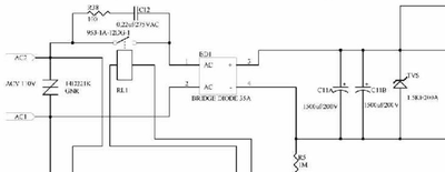
Schemactics:

1- AC Input 120VAC

2- MOSFET stage

3- Nameplate

Register to Reply
Pathfinder Tags: dc motor mosfet PWM Snubber
Interested in this topic? By joining CR4 you can "subscribe" to
this discussion and receive notification when new comments are added.

Good Answers:

These comments received enough positive votes to make them "good answers".

"Almost" Good Answers:

Check out these comments that don't yet have enough votes to be "official" good answers and, if you agree with them, vote them!
Guru

Join Date: Dec 2010
Posts: 1686
Good Answers: 116
#1

Re: Determining the Need of a Snubber in this Application

06/23/2018 4:44 PM

I do not think you will need a snubber.

Circuit diagram 1 - AC input

120VAC power is usually earthed. So putting another earth ground on the outlet side can be real trouble. Your symbol for GRND1 is a real earth or at least power outlet earth, GRND2 symbol a common [COM] - appropriate labels/symbols needed. Even without, your circuit common is switching between line & neutral every half-cycle. You do not have any RF bypass capacitors or filters to stop noise going back into supply

Circuit diagram 2 - MOSFET

You have a diode across motor. Leakage inductance of motor may limit current spikes in mosfet or capacitance might encourage them. Diode will prevent +ve voltage spikes. You have to put small non-inductive resistor in FET source to check peak/mean current and use oscilloscope to measure that and drain voltage peaks

There are imponderables, such as amount of noise generation/conduction & radiation with [10 kHz repetition of fast switching] you will get which depend on physical layout and very much on length of lead to motor (antenna).

Modern products face strict EMC requirements.

Nameplate - 27 amps is considerable current. I think the power level is enough to involve modern product rules which require good power factor and waveform/harmonics limits to prevent distortion of AC supply.

Could not trace motor type on Leeson site. Presumed 90% efficiency means 270 amp locked-rotor 100% duty cycle. I suggest current monitor on mosfet source with overcurrent shut-down - it will not last long at 800W x 0.5'C/W= 400'C theoretical junction temp (ignoring heat sink rise!).

Register to Reply
Commentator

Join Date: Jun 2018
Posts: 57
#2
In reply to #1

Re: Determining the Need of a Snubber in this Application

06/23/2018 7:23 PM

Hi,

I might have used ground symbols wrongly. I just wanted to point out that I have two different grounds, the 5V ground and the "Vbus" ground, which are "DC grounds". Since I have optoisolation, I have different grounds. Could you explain to me again the problem with my 120VAC grounding scenario?

I plan to add an EMI filter to the 120VAC input. Is that okay?

About the current monitor, as you can see in the MOSFET schematic, I plan to use the TLI4970 which has overcurrent detection. What do you think of that chip?

As for the resistor at the FET source, do you mean something like this? Resistor0.01OHMS

Register to Reply
Guru

Join Date: Dec 2010
Posts: 1686
Good Answers: 116
#3
In reply to #2

Re: Determining the Need of a Snubber in this Application

06/24/2018 5:45 AM

A 25 amp full-scale chip will just read "over-range" above 25 amp - 50 amp scale chip may be better choice with 27A continuous motor - often 2 x full load torque is required. It is always bad news to drive something at full rating - no margin for overload.

Better to put Hall device over source lead of FET where it is not subject to 180V p--p @ 10 kHz. If common shared with FET drive, its Fast overcurrent O/P can be hard wired to latch off & shut down FET drive at 50 amp. Obviously PWM loop can limit current, but may be too slow to save FET on short circuit or motor stall/jam.

You will not need Resistor0.01ohm if using hall sensor.

No time to explain more - got to sing in Beethoven's Choral Symphony today.

Register to Reply
Guru
Engineering Fields - Electrical Engineering - Been there, done that. Engineering Fields - Control Engineering - New Member

Join Date: Dec 2008
Location: Long Island NY
Posts: 15603
Good Answers: 982
#4

Re: Determining the Need of a Snubber in this Application

06/24/2018 10:13 AM

As others have pointed out the snubber is your diode in parallel with your motor. This would fine for just a solenoid. However, you might have a complication due to using the low impedance of just a diode for a snubber. That complication will be the amount of time it takes for the snubber diode to dissipate the flyback energy of the motor inductance and the mechanical energy being braked.

Dynamic braking may not be a concern, for many treadmills, but the stored or driving mechanical energy will be dissipated somewhere by friction or heat in the circuitry. The time constant for an inductance is t=L/R so having just the non-linear impedance of a power diode will make this awkward to calculate but a nominally low impedance will extend the amount of time to reach the five time constants norm. This will make slowing down the treadmill difficult unless a mechanical drag is always applied.

What is even more difficult to quantify is how much mechanical energy will be converted into the heat of your snubber network. A hamster trying to outrun the speed set by the treadmill motor controller will not be a problem but if this treadmill is for a horse or olympic athlete then this just might roast your diode. A resistor in series with the diode will now allow two devices to dissipate both energies (the inductance energy at a much faster rate) but at the risk of generating a voltage high enough to breakdown the MOSFET. What should become apparent is dissipating heat in whatever snubber network gets used will be a concern.

Since you are using a MOSFET one must always consider the reverse biased body diode in any analysis.

I'm puzzled why you are measuring the current applied to this motor via the control transistor. This current will be proportional only to the torque produced by the motor to accelerate the mechanical load and not the motor velocity. I can see proper ways to use this aspect.

__________________
"Don't disturb my circles." translation of Archimedes last words
Register to Reply
Commentator

Join Date: Jun 2018
Posts: 57
#5
In reply to #4

Re: Determining the Need of a Snubber in this Application

06/24/2018 11:03 AM

So, as pointed out before, do you suggest to place the current monitor at FET source? Also, as shown in the schematic the power diode is the RURG5060, which is 600V/50A and the power MOSFET 250V/128A. Might this diode get damaged as you said?

Register to Reply
Guru
Engineering Fields - Electrical Engineering - Been there, done that. Engineering Fields - Control Engineering - New Member

Join Date: Dec 2008
Location: Long Island NY
Posts: 15603
Good Answers: 982
#6
In reply to #5

Re: Determining the Need of a Snubber in this Application

06/24/2018 11:21 AM

No, the current monitor will work very well to track how much torque the motor produces to move the treadmill. Putting it at the FET source will just add the much smaller IGS to the IDS current you are already monitoring. If this is what you wish to monitor then this is fine. If you have another intent then state the intent. My puzzlement is about what you wish this measurement to provide you not where to measure this.

As for the diode it certainly might become damaged, it might not. Just like my uncertainty for monitoring the current, this all depends on facts implicitly asked for but not presented.

People have put a Ferrari on a treadmill. They then call it a dynamometer but is still just a treadmill.

__________________
"Don't disturb my circles." translation of Archimedes last words
Register to Reply
Commentator

Join Date: Jun 2018
Posts: 57
#7
In reply to #6

Re: Determining the Need of a Snubber in this Application

06/24/2018 11:34 AM

Basically I want to monitor the current to provide kind of overload protection, like a shut down function. Certainly, the TLI4970 provides overcurrent detection interrupt, which I find it a nice feature.

Register to Reply
Guru
Engineering Fields - Electrical Engineering - Been there, done that. Engineering Fields - Control Engineering - New Member

Join Date: Dec 2008
Location: Long Island NY
Posts: 15603
Good Answers: 982
#8
In reply to #7

Re: Determining the Need of a Snubber in this Application

06/24/2018 11:45 AM

A short circuit in the motor certainly could cause an overcurrent condition. This part now makes sense to me.

__________________
"Don't disturb my circles." translation of Archimedes last words
Register to Reply
Guru

Join Date: Oct 2006
Location: Surrey BC Canada
Posts: 1571
Good Answers: 42
#9

Re: Determining the Need of a Snubber in this Application

06/24/2018 12:33 PM

120vac 1 phase input may not provide the expected output voltage.

To efficiently use your input circuit you need to draw current for more of the available conduction angle. As it stands I would anticipate closer to 100 volts average output. As the filter capacitor "grows" in size you conduct for a shorter and shorter period on the input diodes, and the current increases to keep the input power matching the output power. I can easily see exceeding 100A peek on the input while drawing 27 amps average on the output side.

With many motor controls there are 2 control loops - the inner loop being motor current, and the next outer being for speed or voltage. This allows controlling and limiting motor current / torque and then controlling the speed.

A full wave SCR controlled rectifier would be a much simpler circuit. For pennies more adding a "regen" SCR bridge would allow for four quadrant operation of the motor.

A more complex circuit could use 4 mos fets as the power conversion from Ac to DC. The topology would be similar to an "active front end" for a four quadrant low harmonic regen drive. Also reference matrix converter.

Register to Reply
Commentator

Join Date: Jun 2018
Posts: 57
#10
In reply to #9

Re: Determining the Need of a Snubber in this Application

06/24/2018 1:58 PM

Many treadmills DC controllers use a relay to switch the 120VAC to the bridge rectifier input. I've replaced the relay system by a triac system with zero crossing. Do you mean this is no an efficient way to do what I intend? 100A peak would probably roast my circuit. My bridge rectifier is 35A, the triac as well.

A full wave SCR controlled rectifier would probably change the whole project idea, since I'm using PWM driven system. But as you say, it could be easier.

Register to Reply
Guru

Join Date: Oct 2006
Location: Surrey BC Canada
Posts: 1571
Good Answers: 42
#11
In reply to #10

Re: Determining the Need of a Snubber in this Application

06/24/2018 7:00 PM

The delta voltage on 4400UF at 27 amps on a single phase rectifier is 50 volts for the discharge cycle. The charging period will be for about 45 deg out of 180 deg. I think your rms for the diode bridge will be about 55 amps.

You could consider eliminating the power supply caps altogether, and let the FET switch the rectified un-filtered AC line volts.

If you want to filter then you will need about 45,000 uF for a 5 volt ripple. - But the peek and RMS on the filter goes up. If you add inductance on the rectifier output output you can smooth the current ripple.

No matter, you will not achieve full motor voltage with single phase. Three phase you have a chance.

Register to Reply
Commentator

Join Date: Jun 2018
Posts: 57
#12
In reply to #11

Re: Determining the Need of a Snubber in this Application

06/24/2018 8:00 PM

I don't pretend to achieve full motor voltage. For treadmill purposes, 90VDC could be considered the upper limit of the voltage range.

Register to Reply
Guru

Join Date: Dec 2010
Posts: 1686
Good Answers: 116
#13
In reply to #12

Re: Determining the Need of a Snubber in this Application

06/25/2018 8:25 AM

It is not as simple as just having a big reservoir cap on DC supply. The motor inductance/flywheel diode will keep the current rolling through dips in full wave rectified - very big reservoir just increases bridge peak current and mains supply distortion.

Diodes will take considerable overcurrent, they only drop 1 - 3 volts, but FETs can turn on to high current and voltage together and are limited by safe area /time chart and avalanche characteristics when switching off circuit inductance (the bits that are not cancelled by RURG flywheel diode).

Best way to get to grips with this is connect FET up with fast overcurrent hard-wired to FET driver to limit to 25A and measure some motor characteristics [inductive current rise] & diode/FET currents.

But Difficult to connect an [earthed] oscilloscope if FET source & motor are connected to mains via bridge.

Register to Reply
2
Guru

Join Date: Oct 2006
Location: Surrey BC Canada
Posts: 1571
Good Answers: 42
#16
In reply to #12

Re: Determining the Need of a Snubber in this Application

06/25/2018 12:33 PM

OK, if you are happy with 70% speed.

In North America - only use the "plug in" protective earth ground for grounding your chassis and metal parts - to minimize shock hazard.

Use the neutral line as your circuit common.

The usual "plug-in" supply you can only use about 12 amps - higher than that you start tripping breakers.

So your output power will be limited to about 1 k watt.

Treat the project as an experiment to see how the circuit behaves --- to put into production you need another layer of safety and reliability testing, so lets just focus on learning the basics.

lets start with a power limited output of 12 amps - with your input capacitor filter lets just make a few assumptions to get the order of magnitude of componentes. Start by considering the capacitor charged to the peak of the AC line rooot2 x 120vac. The motor inductance is going to draw constant current for a half cycle of 60 hz - The voltage ripple will be found from solving i=C dv/dt - use i = 12 amps, the chosen C, dt = 1/(60 x 2) ---solve for dv --- this is an approximation to ensure you are in the correct order of magnitude for your chosen components - a loose rule of thumb.- practical electronics.

For your PWM stage - consider the motor current as constant because there is a relatively "huge" inductance in the motor. Where will the inductive kick go when you turn of the FET? The FET can turn off faster than a diode can start conducting - so things will ring and oscillate, with the inherent overvoltage spikes. - One solution is to turn the FET on and off at a controlled rate - but that dissipates more power - so there is a balancing act between efficiency and controlling the ringing. Snubbers typically RC networks can be chosen to dampen the ringing. A free wheeling diode can provide a path for the majority of the inductive kick. However if you want 4 quadrant operation then a simple diode across the DC motor is not practical.

Start by logically trying to follow what the "gross" circuit components are - a simple motor model of a series inductance and resistance, and a CEMF (stalled rotor and the CEMF = 0). Motor L/R time constant could be 100msec or longer. Once those pieces are in place think through and sketch out what the anticipated wave forms will be.

Once the gross circuit is figured out, then start thinking about stray capacitance. The motor becomes a somewhat complicated LRC circuit that is not well defined. How are you going to stop it from ringing? How will you design to swamp the parasitic components?

As a learning tool - build the circuit and LEARN FROM IT.

Just copying snippets of existing circuits does not demonstrate understanding.

Learn from the masters - understand and predict your circuit operation - experimentally test your circuit.

Register to Reply Good Answer (Score 2)
Commentator

Join Date: Jun 2018
Posts: 57
#17
In reply to #16

Re: Determining the Need of a Snubber in this Application

06/25/2018 2:41 PM

Thank you so much.

I really don't pretend to copy my project of existing circuits. I just try to see how other designers think. It works as a starting point for me as a newbie when it comes to design. Then, with experience I can embark on new projects all by myself.

To be honest, that's really what I want, to learn the most from this project. I study Electronics Engineering, and in my country, people are not taught how to design, so I've had to put extra effort by myself because I want electronics design to be part of my professional career.

Back to technical stuff, as you say, I will treat the project as an experiment to see how the circuit behaves, I can't for now put it into production, but I certainly have to present a physical project in my college, so that's why I will make a PCB, not the best, but I will try my best to get at least acceptable results as a first attemp project.

So far, I've selected every component of this project by myself. From a resistor to the power switching elements. I haven't been able to simulate the circuit though. Maybe LTspice could work if I wish to simulate it.

I think that many things will have to be tested experimentally to see what exactly is happening. For example, I could build the circuit without the RC snubber you mentioned to see what happens. But the most important thing is that I should be able to understand and predict my circuit operation, which I find it a real challenge. I really want to avoid blowing something when testing the PCB. And if it does, I would take it as a learning process.

Register to Reply
Guru

Join Date: Oct 2006
Location: Surrey BC Canada
Posts: 1571
Good Answers: 42
#18
In reply to #17

Re: Determining the Need of a Snubber in this Application

06/25/2018 4:17 PM

That is a good starting philosophy.

To put things in perspective - I began my power electronics when all I had was a slide rule. Simulation software was another decade away. By making rather broad assumptions (like the motor current will be constant for the 1/2 cycle we are interested in) we could get order of magnitude results. When you consider any given transistor could have a beta between 50 and 200 - order of magnitude is what you have to live with!

Your project is luckily in the "audio spectrum" so much of the modelling can be done with first order models - you can solve that by hand.

For the ringing part - you are aware it can happen - it can be very high frequency - it is a nuisance for your project - but you can filter to kill it and it won't materially change the design. For the low frequency components - you know the motor has a significant inductance, the L/R time constant of the motor we give you a heads up it is a long time for your design - so where will that energy go?

Just think it through, you have an input power stage - the power into it has to supply the output power - anticipate the waveform - simplify to the safe side - and size components to match. Do the same thing for the output stage.

Just as a side note - the pre-charge circuit for many AC motor controls is simply a current limiting resistor - once the capacitor voltage is high enough it closes a relay contact around the resistor. Very efficient and no (significant) power loss across the contact.

Register to Reply
Commentator

Join Date: Jun 2018
Posts: 57
#19
In reply to #18

Re: Determining the Need of a Snubber in this Application

06/25/2018 4:52 PM

Yeah, I've seen plenty of VFDs (Variable Frequency Drive) that use a current limiting resistor and then close a relay contact.

In my case, I would want to control when the bridge is going to be fed. That's why I chose that optotriac circuit. Could be done with the relay as well. I will get away with the input circuit that I posted first to see what happens according to what has been analyzed. I'm going to start the PCB soon. For the MOSFET and motor stage, I will see what else I can consider that is within my reach. Maybe leave like that. But I will consider more the ringing part of course.

Basically the power stage of this project is the most critical one. The microcontroller stage (which in my design is optoisolated from the motor voltage) is okay for now. This controller will adjust the duty cycle according to speed and current feedback. But that's out of the topic of this post.

Register to Reply
Guru

Join Date: Oct 2006
Location: Surrey BC Canada
Posts: 1571
Good Answers: 42
#20
In reply to #19

Re: Determining the Need of a Snubber in this Application

06/25/2018 6:14 PM

On a recent design I simply used a resistor and a small capacitor in the gate lead of the FET to slow the turn on / off time. I was getting ringing in the 10's of MHz range. By limiting the rise time to 1 usec significantly reduced the ringing.

Register to Reply Off Topic (Score 5)
Guru

Join Date: Dec 2010
Posts: 1686
Good Answers: 116
#21
In reply to #19

Re: Determining the Need of a Snubber in this Application

06/26/2018 9:00 AM

The simple resistor & relay inrush surge limit is the way to go.

Supply resistance [16kA S/C @ 115v] = 7 milliohm But note that 10 kVA, 230V out Centre-tapped single phase supply transfo may be 100 mohm @ 115V - USA denizens please quantify.

2 metres 6sq.mm copper power cord = 12 mOhm

Ditto - in wall = 12 mohm

2 x 2200 μF 200V caps Effective series resistance @ 100 Hz (reactance 0.36Ω) = 35 mohm.

EMC filter Schaffner FN350 = 7 mohm

TOTAL 73 mohm [I left out diodes & Triac but may be 20 mohm more]: Surge Current 115/.073 = 1600 amp: RC = 0.32 millisecond.

Current will fall exponentially to 220A after 1 ms. Surge rating of bridge 400A/8.3 ms 1/2 sine@25 Celsius. I2t of 660 may hit minimum of 32A HBC fuse.

Triac must carry 30 amp with approx 1.5V drop - a significant heat-sink size/cost & power loss operating.

Supposing bridge diodes & Triac conduct for 30 degrees in 180, leaves 7 ms to supply from 4400 μF. Conducting 1/6 of time requires 30 amp x 6 = 180 amp during conduction. As pointed out by other post, volts drop on caps about 40V @ 30 amp while diodes not conducting. N.B. That 80mohm odd circuit resistance will drop some 14V @ 180 amp.

You can see why heavy current single-phase full-wave rectifiers traditionally used inductor input filters to cut surges and spread conduction angles.

Without capacitors to cause surges, a 3 phase, 6 diode bridge output will only dip about 15% from peak, while mean value is 95% of peak. Conduction angles are 60 degrees. You can see why heavy current equipment is usually 3 phase.

Register to Reply
Guru
Engineering Fields - Electrical Engineering - Been there, done that. Engineering Fields - Control Engineering - New Member

Join Date: Dec 2008
Location: Long Island NY
Posts: 15603
Good Answers: 982
#14
In reply to #10

Re: Determining the Need of a Snubber in this Application

06/25/2018 10:00 AM

I did not examine your AC supply circuit diagram for your thread question is about the snubber circuit. I too have concerns here.

First, here in the USA a 30+ ampere 120 VAC outlet (required for having a 30 ampere fuse) is not a common mains outlet. They do exist but the very heavy gauge (6 AWG) wiring required to connect a 50 ampere outlet to a breaker panel is not a trivial expense for the building contractor. So where one of these outlets exists is a purpose built installation.

Second, no galvanic isolation of a transformer is provided. As such a very methodical analysis of all interacting voltage and current sources and their ground references must be considered. For instance, in the USA most 120 VAC wiring consists of a hot wire and a neutral wire. By definition a neutral wire is bonded to ground. As such if your AC supply circuit will be used in the USA you will have charging currents running through your diode bridge directly to ground as soon as this is plugged in. Your diode bridge will quickly release the carefully installed inherent smoke. Remember that all electric parts only work when the inherent smoke remains contained.

Third, the peak voltage of 120 VAC is just under 170 V. By bridge rectifying and storing this voltage on your capacitors you will have a peak voltage of 165 V not the 125 VDC your motor is rated to handle.

Lastly, it looks like the relay circuit you attempt to replace with an SCR circuit is a safety feature. It prevents a treadmill from running after mains power is restored. As a student I would not alter or replace any given safety feature.

__________________
"Don't disturb my circles." translation of Archimedes last words
Register to Reply Score 1 for Good Answer
Commentator

Join Date: Jun 2018
Posts: 57
#15
In reply to #14

Re: Determining the Need of a Snubber in this Application

06/25/2018 10:54 AM

Look at the picture attached below:

It's a fragment of a schematic from a treadmill. Some stuff can't be well appreciated, but is easy to note that they have used a relay contact before the bridge rectifier. The relay is controlled by another circuit not shown. When that treadmill is given the command to start running, the relay contact closes allowing the bridge to feed from the 120VAC. In my case, I've just replaced the relay contact with a triac circuit as shown in my first post. I will give a signal to the optotriac to enable the power triac, which is like the relay in the circuit above. It's like a SSR. I just want to take advantage of the zero crossing feature, which is not provided by the relay. The relay could close at the peak of the wave, and I want to avoid that.

Register to Reply
Register to Reply 21 comments

Good Answers:

These comments received enough positive votes to make them "good answers".

"Almost" Good Answers:

Check out these comments that don't yet have enough votes to be "official" good answers and, if you agree with them, vote them!
Copy to Clipboard

Users who posted comments:

67model (4); GW (5); redfred (4); XaviPacheco (8)

Previous in Forum: LED Light Bulbs   Next in Forum: AC Resistance vs DC Resistance

Advertisement