Previous in Forum: Fuses on Ungrounded DC Systems   Next in Forum: When Does One Draw The Line On EMI?
Close
Close
Close
8 comments
Rate Comments: Nested
Anonymous Poster #1

Potential Transformer

11/09/2016 5:58 AM

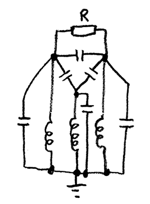
The PT ratio is 6kV/0.11kV. The Potential transformer connected is of star-star (grounded at both sides). The Phase voltage measured at the secondary of the potential transformer is constantly fluctuating but the line voltages are normal. The phase to phase voltages are normal. The system is ungrounded system.

Possible reasons:

1) Under normal conditions, with line to ground capacitances balanced, the charging currents add to zero. in actual practice the line to ground capacitances are not exactly balanced and hence the ground may have attained some voltage or potential. Therefore, the individual phase voltages to ground may not be equal causing voltage fluctuations.

2) Voltage Transformer’s magnetizing impedance and line to ground capacitance can cause resonant condition. Voltage transients caused by switching can cause this condition.

This happens in a Incomer, If we start giving loads the phase to neutral voltage becomes normal.

Why and What is happening?

Reply
Interested in this topic? By joining CR4 you can "subscribe" to
this discussion and receive notification when new comments are added.
Guru
Safety - Hazmat - New Member United States - US - Statue of Liberty - New Member Engineering Fields - Chemical Engineering - Old Hand

Join Date: Mar 2011
Location: Lubbock, Texas
Posts: 14331
Good Answers: 162
#1

Re: Potential Transformer

11/09/2016 1:43 PM

Sounds like homework, and the dog ate mine last night!

__________________
If it ain't broke, don't fix it. Just build a better one.
Reply
Guru

Join Date: Dec 2010
Posts: 1686
Good Answers: 116
#2

Re: Potential Transformer

11/10/2016 9:14 AM

It would be helpful if you gave, for your fluctuations, the voltage magnitude e.g. maximum and minimum and period e.g. time between maximum values.

Also, what meter is used - moving iron pointer analog meters are dependable, but digital AC meters can cause fluctuating readings if the frequency varies (they measure over a time equal to one or several cycles, which is only true if frequency is exactly right - most have an internal switch to select 50 or 60 Hz)

From your description, you have an ungrounded 3 wire 6 kV system. This is often applied on a small system as a necessity to keep cost down. A single ground can be tolerated for a time, if a "tree branch" it can even be cleared without disconnecting anyone. There is the problem that the location of a fault is untraceable, except by opening each feeder in turn, until the one with a fault is opened. There is insufficient current into an earth fault to operate feeder earth current relays.

There are reasons why any large size system is earthed, directly or by a resistance. The use of earth current relays to disconnect only the faulty circuit quickly and automatically is one.

Another is the build-up of capacitance to ground as the system grows. Eventually, this can get to a size which resonates with PT primary inductance at power frequencies. In effect, the resonance increases the impedance to ground, Inductance is "tuned out" by capacitance [parallel inductance and capacitance at resonance ideally have, with zero losses, infinite impedance].

This increased impedance gives greater voltages for any given injection of charge by switching or lightning/faults and leads to overvoltage of PTs and their sudden failure. The "killer" is usually an arcing ground fault which causes many more spikes than less frequent switching/lightning events.

The Δ capacitances line to line and Y capacitances to ground are interconnected, so resistance load across the Δ capacitors does have a damping effect on resonances to ground.

The sketch shows the PT primary inductances and the capacitances, with one load resistance.

Note that if the magnetising power of one primary of the PT is 50 VA at 4000V, the magnetising current is 0.0125 amps. At 4000V 50 Hz, a capacitance of 0.01 microfarad is 320000 ohms, which draws 0.0125 amps, compensating the inductive current, theoretically giving exceedingly high impedance to ground at 50 Hz.

You have mentioned the possibility of unequal capacitance to ground, you should also consider the possibility of phase "swinging" of the supply - real supplies do not have a perfectly steady frequency or phase.

Reply
Anonymous Poster #1
#3
In reply to #2

Re: Potential Transformer

11/10/2016 10:22 AM

Dear 67Model,

Thank you for your reply.

The followings are the measured/calculated values by the digital relay in the said Incomer. The readings are fluctuating constantly.

Va Primary 2.030kV to 4.932kV (fluctuating)
Vb Primary 3.670kV
Vc Primary 3.587kV
V0 0.894kV to 1.527kV (fluctuating)
V1 3.608kV
V2 0.016kV
Vab 6.234kV
Vbc 6.221kV
Vca 6.265kV
Vn 2.529 to 3.680kV (fluctuating)
Va angle 0 degree
Vb angle 98 to 160 degree (fluctuating)
Vc angle 229 to 263 degree (fluctuating)
Vn angle 10 to 258 degree (fluctuating)
Vab angle 315 degree
Vbc angle 72.707 degree
Vca angle 216.597 degree

The readings measured at the secondary of the PT using digital AC meter also fluctuates constantly

Reply
Guru

Join Date: Dec 2010
Posts: 1686
Good Answers: 116
#5
In reply to #3

Re: Potential Transformer

11/11/2016 7:31 AM

Max/Min values for Va, V0, Vn have similarities. It is not clear if you have separate PTs for line-line voltage - normal readings for line-line suggest you do. Vb and Vc normal suggest actual Va is normal and Va measurement has interference.

Considerable variation of Va and confirmation by an independent meter (you did not give maximum or minimum for that or if it was at terminals of PT itself) suggests a noisy "spike"signal which can cause digital instruments to give varying readings.

It is useful to have a moving iron or moving coil/rectifier analog instrument, they do not give erratic readings due to electromagnetic interference nor do they give unintelligible "sampling" errors on varying or distorted voltages, the pointer just flickers or "cycles" around(EMI test houses use them to be sure the clever electronic stuff, especially their own, is not deceiving them).

Sparking/shorting in a faulty PT, HT fuse/connection or LV wiring could be the problem, the analog meter would probably show an unsteady low reading.

Use an oscilloscope on the Va PT signal if you have one.

Swapping the Va and Vb inputs at the relay could confirm that the Va channel of the relay & Vb channel are the same - you will have to ensure this does not bring up a protection trip - you may have to isolate the trip contact (after considering risk!!!).

An AM radio - amplitude modulated, usually working in 150 -1600 kHz band can be useful to detect sparking (tune off any radio station), if held near the Va wiring etc. They usually have internal ferrite rod antenna which is directional- be very careful of safety of any swing/pull out metal antenna.

I have other ideas, but no time before leaving home.

I would note that the "PT fault" explanation fails, if, as you wrote, applying a load to system gives normal Va readings.

Reply
Guru

Join Date: Dec 2010
Posts: 1686
Good Answers: 116
#6
In reply to #3

Re: Potential Transformer

11/12/2016 4:26 AM

To continue from post #5...

  1. Look carefully at what is connected to Va, Vb, Vc PTs.....anything different? Any load on Va, say a battery charger, which might be "noisy"? Is Va load much less than Vb,Vc?
  2. Try disconnecting any loads, other than the relay you took voltages off, from Va PT, to see if that stops the problem.
  3. Are the Va,b,c PTs well loaded compared to their rated burden? What are the loads measured?
  4. Since having a 6kV load on your system stops the fluctuation, adding resistive load to PT secondary(s) may stop problem at no-load. Having PT resistive load is a palliative for the problems of systems only earthed by PTs.
  5. Note that PT calibrated accuracy is at or near the rated burden, applying a suitable load will not increase errors.

67model

Reply
Anonymous Poster #1
#7
In reply to #6

Re: Potential Transformer

11/17/2016 1:14 AM

Hi 67model,

Thank you!!.

"Since having a 6kV load on your system stops the fluctuation, adding resistive load to PT secondary(s) may stop problem at no-load. Having PT resistive load is a palliative for the problems of systems only earthed by PTs."

But How does the 6kV load add resistive load to PT?

Reply
Guru

Join Date: Dec 2010
Posts: 1686
Good Answers: 116
#8
In reply to #7

Re: Potential Transformer

11/17/2016 6:16 AM

The point is that, by transformer action, an LV winding resistive load on PT adds resistance to ground on the 6 kV system. You have written that when you load the 6kV system, by turning on a site load, the fluctuating reading becomes steady. If you load all 3 phases by loading all three "line to ground" PTs, this will give maximum damping of any resonances.

My impression is (you have not given any details of grid transformer rating or current demand of your load) that you have a delta transformer winding connected by a short length of 6 kV open wire line to your system (on which your load breakers are open when you have fluctuating readings).

This 6kV system would appear to have very high impedance to ground. It is ungrounded except by the PTs. As I pointed out, with electronic relays the load on the PTs may be very small - also that ungrounded systems can have have high resonance voltages.

I cannot see the diagrams of the loads on your PTs, nor can I see what other loads are on the PT which might affect the relay from which you are taking voltage readings. Neither can I disconnect equipment which might interfere with your relay, measure at PT LV terminals direct rather than at relay, or connect an electric toaster or kettle or other available resistive load or see what your relay does, apart from giving voltage readings.

Although a PT fault is possible, loading at 6kV line-line would not affect the "PT to ground" primary voltage. Also, since two other line voltages to ground are indicated "normal", it is not possible the third voltage is not normal in reality.

Have you been able to measure the "fluctuating" PT voltage at the relay terminals with a simple moving iron or moving coil meter?

Reply
Guru
Engineering Fields - Power Engineering - New Member

Join Date: May 2007
Location: NYC metropolitan area.
Posts: 3230
Good Answers: 444
#4

Re: Potential Transformer

11/10/2016 11:59 PM

Have you considered testing the PTs for internal faults? I suspect that there is a turn-to-turn or turn-to-ground intermittent/arcing fault. You can easily verify this by swapping the transformers to see if the problem travels or stays with the original phase. A look at the secondary waveforms with an oscilloscope might provide a clue also.

__________________
“Tell me and I forget. Teach me and I remember. Involve me and I learn.” Ben Franklin.
Reply
Reply to Forum Thread 8 comments
Copy to Clipboard

Users who posted comments:

67model (4); Anonymous Poster (2); James Stewart (1); RAMConsult (1)

Previous in Forum: Fuses on Ungrounded DC Systems   Next in Forum: When Does One Draw The Line On EMI?

Advertisement