"Thermoelectric devices, which can generate power when one side of the device is a different temperature from the other, have been the subject of much research in recent years. Now, a team at MIT has come up with a novel way to convert temperature fluctuations into electrical power. Instead of requiring two different temperature inputs at the same time, the new system takes advantage of the swings in ambient temperature that occur during the day-night cycle."

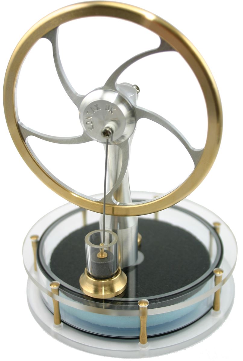
The team's test device, which has been deployed on the roof of an MIT building for several months, was used to prove the principle behind their new energy-harvesting concept. The test device is the black box at right, behind a weather-monitoring system (white) and a set of test equipment to monitor the device's performance (larger black case at left). Credit: Justin Raymond
https://www.sciencedaily.com/releases/2018/02/180215124853
It's interesting how this works. They have a heat engine (probably a Thermoelectric module) between the environment and a specially constructed material which has both a high thermal conductivity and high heat capacity. In the daytime, heat flows through the heat engine into this "sink" and in the nighttime heat flows in the other direction.
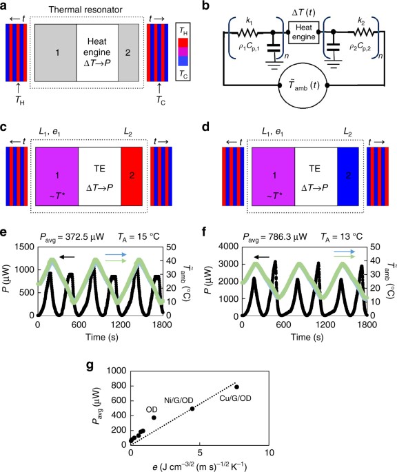
"Application of ultra-high thermal effusivity materials in a thermal resonator. a A general schematic of a thermal resonator. A heat engine is encased between two thermal masses (1 and 2), which convert input temperature fluctuations—shown here as oscillating in time (t) between hot (red; TH = T0 + TA) and cold (blue; TC = T0 − TA)—into a spatial temperature difference, ΔT(t)ΔT(t), that is converted to power (P) by the heat engine. b A thermal circuit demonstrating the operation and modeling details of a thermal resonator. Input, temperature fluctuations, T˜amb(t)T̃amb(t), are applied and transformed into a spatial temperature difference by tuning the system’s thermal resistances (k1,k2,L1,L2)(k1,k2,L1,L2) and capacitances (ρ1Cp,1,ρ2Cp,2)(ρ1Cp,1,ρ2Cp,2). c, d General schematics of a thermal resonator resembling the devices constructed and tested in this work, which incorporate a high thermal effusivity PCM as thermal mass 1 and a negligible thermal mass as 2. The schematics are similar to a, except the heat engine has been replaced by a thermoelectric (TE) and the anticipated temperature distribution throughout the device has been shown. Thermal mass 2 quickly responds to the temperature of the environment (hot, c or cold, d). Thermal mass 1 has a phase transition temperature (T*) near the median temperature of oscillations and mainly exists at this temperature. e Power profile (black) and input temperature profiles (blue, green) for a thermal resonator incorporating OD as thermal mass 1 (Supplementary Note 7). The time-averaged power output (Pavg) and temperature oscillation amplitude (TA) are also provided. f Power profile (black) and input temperature profiles (blue, green) for a thermal resonator incorporating Cu/G/OD as thermal mass 1 (Supplementary Note 7). The time-averaged power output (Pavg) and temperature oscillation amplitude (TA) are also provided. g Time-averaged power output (Pavg) of thermal resonators as a function of the thermal effusivity of thermal mass 1 (Methods, Supplementary Note 6). The linear fit of the data with the intercept forced through the origin is also shown, and the slope of the fit is 111, with the units determined by the axes. The six unlabeled data points in ascending order of thermal effusivity correspond to styrofoam, neoprene foam, wood, PVC, Teflon, and neoprene rubber. For PCMs (OD, Ni/G/OD, Cu/G/OD), thermal effusivity is given by Supplementary Eq. (16)"
*****
The "sink" is a metal matrix infused with graphene (for thermal conductivity) and a phase change material (octadecane) for high heat capacity.
Here is a paper describing the details.
https://www.nature.com/articles/s41467-018-03029-x


 Re: System draws power from daily temperature swing

/cdn.vox-cdn.com/uploads/chorus_image/image/58755585/Screen_Shot_2018_02_20_at_10.27.15_AM.0.png)
"Almost" Good Answers: