Previous in Forum: MCCB and its Ics and Icu   Next in Forum: 11000kV Wires vs 11000kV to 220V Transformer
Close
Close
Close
33 comments
Rate Comments: Nested
Guru

Join Date: Oct 2006
Location: 44.56024"N 15.307971E
Posts: 8277
Good Answers: 270

Determining Solenoid Condition

05/19/2018 5:19 AM

It's me again,guys,seeking some input on another project.

I would like to determine the condition of solenoids in the field while in operation in real time.

Everyone know that when you energize an inductor,when it is de -energized there is a voltage generated in the opposite direction of the applied voltage when the magnetic field collapses.Referred to as a flyback voltage.

Now,consider a plunger-type solenoid.

When it retracts upon demagnetization,there will be a flyback voltage generated.

The retraction is via a spring.

I would like to be able to detect a weak spring or a delayed return using the flyback waveform voltage characteristics.

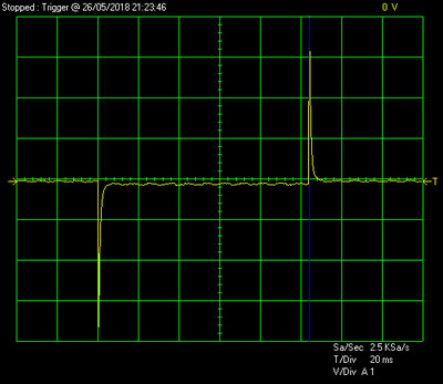
I have not scoped these signals yet,but I would think there would be a difference in the wave form.

I realize I would need a type of waveform analyzer to compare signals and trigger an alarm or message when a defective or weak spring is detected.

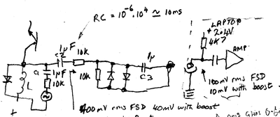
All of the solenoids have a reverse biased diode across the coil,so I am thinking of a low value resistor in series with the diode to give a voltage proportional to the current.

A peak voltage level sensor may be all that is required to distinguish good vs bad solenoid.

I realize there will be some software involved,and that is a different matter altogether,but at the present time I would like recommendations on the hardware required.

The implementation will involve hundreds of inputs,so the signals will have to be multiplexed.

Response time per solenoid signal is relatively slow,as long as it is below 5 ms.

Any suggestions as to a particular IC,or group of IC's to do this,considering there are approximtely 300 solenoid to monitor?

An output signal would be desired when certain parameters are exceeded.

As always,I am very appreciative of everyone's valuable time and input on this subject.

__________________
"A man never stands so tall as when he stoops to help a child." "Never argue with a stupid person.They will drag you down to their level and beat you with experience" "To create an apple pie from scratch, first you must create a universe"
Register to Reply
Pathfinder Tags: Solenoid health detection
Interested in this topic? By joining CR4 you can "subscribe" to
this discussion and receive notification when new comments are added.

"Almost" Good Answers:

Check out these comments that don't yet have enough votes to be "official" good answers and, if you agree with them, vote them!
Guru

Join Date: Mar 2007
Location: by the beach in Florida
Posts: 33392
Good Answers: 1817
#1

Re: Determining Solenoid Condition

05/19/2018 9:29 AM

That's all very interesting, but any solenoid I've seen go bad it was an open circuit in the coil, or some trash in the line that got caught in the plunger keeping the valve partially open....I don't think I've ever seen a spring wear out....Wouldn't a better approach be to just check coil temperature?...or coil resistance?

In any case I found these links that may be of interest...

https://www.nxp.com/docs/en/data-sheet/MC33811.pdf

http://www.ti.com/lit/ds/symlink/drv103.pdf

https://www.nrc.gov/docs/ML0403/ML040360191.pdf

__________________
All living things seek to control their own destiny....this is the purpose of life
Register to Reply
Guru

Join Date: Oct 2006
Location: 44.56024"N 15.307971E
Posts: 8277
Good Answers: 270
#4
In reply to #1

Re: Determining Solenoid Condition

05/19/2018 12:14 PM

These are not solenoid valves,they are a cylindrical solenoid operated "piston" shaped armature that is spring return.

There has never been a coil failure over millions of operating hours,they are inherently current limited and overload protected.

In normal operation they are activated for only about 100 milliseconds,with a duty cycle of about 10%.

The problems occur when the solenoid becomes jammed and product does not dump,creating a "log jam" behind it.

There is currently no feasible method to determine imminent failure of an armature "piston" that actuates or returns too slowly.The purpose of this proposal is to know when an armature is slow to return or engage,and schedule a replacement during a maintenance window.I am sure that a hall effect or optical sensor would work,but the expense would be too high.

A shielded pair or coax fore each gate signal would be better.

It might even be practical to monitor the signal at the controller source ,but each solenoid would have to be individually calibrated to compensate for cable length,resistance,etc.

Theoretically,a new solenoid could be characterized when installed, by energizing it,and these measurements would be used for future reference.

I am sure there are experts that could create the software required,but my main concern is the hardware at this point.

Theoretically,a new solenoid could be characterized when installed, by energizing it,and these measurements would be used for future reference.

I am sure there are experts that could create the software required,but my main concern is the hardware.

Thanks for your feedback on this,and I will review your links later as I have prior commitments to attend.

__________________
"A man never stands so tall as when he stoops to help a child." "Never argue with a stupid person.They will drag you down to their level and beat you with experience" "To create an apple pie from scratch, first you must create a universe"
Register to Reply
Guru

Join Date: Oct 2006
Location: 44.56024"N 15.307971E
Posts: 8277
Good Answers: 270
#8
In reply to #4

Re: Determining Solenoid Condition

05/19/2018 2:25 PM

OOPS! Please excuse the double-speak..I accidentally hit my my cut/paste feature at the wrong place.

__________________
"A man never stands so tall as when he stoops to help a child." "Never argue with a stupid person.They will drag you down to their level and beat you with experience" "To create an apple pie from scratch, first you must create a universe"
Register to Reply Off Topic (Score 5)
Guru
Engineering Fields - Electrical Engineering - Been there, done that. Engineering Fields - Control Engineering - New Member

Join Date: Dec 2008
Location: Long Island NY
Posts: 15602
Good Answers: 982
#10
In reply to #4

Re: Determining Solenoid Condition

05/19/2018 4:18 PM

Sounds to me like you are focusing on the wrong part. With over a million hours of operation and proper circuit protection these coils continue to be sound. Monitor either the dispensed product (weight, image, optical switch) or possibly this return spring timing with the addition of a fast switch.

__________________
"Don't disturb my circles." translation of Archimedes last words
Register to Reply
Guru

Join Date: Oct 2006
Location: 44.56024"N 15.307971E
Posts: 8277
Good Answers: 270
#11
In reply to #10

Re: Determining Solenoid Condition

05/19/2018 4:44 PM

The coil has never been the problem,and the mechanical portion is the part I am interested in.There are many ways to ensure the proper speed and return of the solenoid,but I am looking for a simple relatively inexpensive method.

Adding switches and sensors will require lots of labor costs as well as material costs,so I am hoping to find a way to analyze the existing wave forms for information.

I hope it can be done at the controller that generates the firing signal to the solenoids.

If the demo proves effective, a modification to the driver board could be implemented to incorporate this feature.

__________________
"A man never stands so tall as when he stoops to help a child." "Never argue with a stupid person.They will drag you down to their level and beat you with experience" "To create an apple pie from scratch, first you must create a universe"
Register to Reply
Associate

Join Date: Jun 2016
Posts: 29
#13
In reply to #4

Re: Determining Solenoid Condition

05/19/2018 11:06 PM

Such quick-switching solenoid systems are now very popular as metering & pressure controls for individual nozzles on agricultural sprayers. Is this what you are working on?

Register to Reply Off Topic (Score 5)
Guru

Join Date: Oct 2006
Location: 44.56024"N 15.307971E
Posts: 8277
Good Answers: 270
#14
In reply to #13

Re: Determining Solenoid Condition

05/20/2018 5:10 AM

This is a mechanical solenoid operated piston,not a valve,but the principle is basically the same.This solenoid is diverting discrete pieces of product instead of a liquid.

It processes over 40000 pieces per hour,and there are hundreds of these solenoids on each machine,of which there are many.

The pieces are single file,and a jam at any one solenoid stops the whole process,and sometimes a logjam of pieces that follow.This requires manual intervention to clear,and sometimes the product is damaged.

I would like to give more details,but I cannot because of restrictions in my contract.

__________________
"A man never stands so tall as when he stoops to help a child." "Never argue with a stupid person.They will drag you down to their level and beat you with experience" "To create an apple pie from scratch, first you must create a universe"
Register to Reply Off Topic (Score 5)
Guru

Join Date: Aug 2014
Location: Port Macquarie N.S.W. Australia
Posts: 1071
Good Answers: 225
#17
In reply to #14

Re: Determining Solenoid Condition

05/20/2018 6:40 PM

If a solenoid fails either due to a weak spring or otherwise, and whether an alarm sounds or not, it appears that the logjam will still occur and need to be cleared.

Perhaps a better approach may be to monitor product movement at each point and alarm and/or stop the conveyor if that movement slows or stops.

This monitor may be able to detect slowed movement of product due to slowing solenoid release even before a total failure occurs and could be set up to alarm only on a slow down and stop the conveyor upon a total jam.

Often a slowed release causes a following item to enter the gate and get stuck by the closing gate thus causing the jam, an approach to overcoming this may be to increase product separation on the conveyor.

Register to Reply
Guru
Engineering Fields - Electrical Engineering - Been there, done that. Engineering Fields - Control Engineering - New Member

Join Date: Dec 2008
Location: Long Island NY
Posts: 15602
Good Answers: 982
#2

Re: Determining Solenoid Condition

05/19/2018 10:56 AM

I'd be surprised if you can see any difference at all in the voltage flyback waveform. You're confusing where and what kind of energy is stored in each component.

(From the above link)

This is the classic description of how a flyback voltage is formed and is very good at teaching the concept of flyback spikes. However, it suffers from being unrealistic. If one were able to achieve this circuit the energy stored in that 10 Henry inductor will have a time constant of one quarter of a picosecond. The parasitic wiring impedance in parallel with the inductor will surely be smaller than 40 tera-ohms. What is accurately portrayed in the linked article but not made explicit is a relaxing (discharging) inductor is a current source and not a voltage source. The voltage waveform will be determined by the coil and the discharge path impedance. Keeping the discharge path impedance fixed for waveform comparison is critical.

The crux of the problem is time. If one slows down the inductor discharge path time constant low enough to see an inductance change as the slug is moved by the spring the peak discharge voltage will be so small it will be very difficult to measure.

Also by slowing down the coil release the magnetic force on the slug will also be gradually released. The non-linear factor of stiction may not be overcome by the spring. Thus by trying to measure for a sticky spring you may make it more likely to stick.

__________________
"Don't disturb my circles." translation of Archimedes last words
Register to Reply
Guru

Join Date: Apr 2010
Location: About 4000 miles from the center of the earth (+/-100 mi)
Posts: 9913
Good Answers: 1141
#3

Re: Determining Solenoid Condition

05/19/2018 12:01 PM

I'm understanding that you are primarily interested in how fast the plunger retracts when current is removed from the solenoid.

The voltage across an inductor is equal to the rate of change of L times I, V=d(LI)/dt, where L is the inductance and I is the current. Normally L is constant, but in this case, when the plunger moves out, L decreases as well as I decreasing. In addition to this, if the plunger is magnetized (which it would be), there would be a voltage generated as it moves out of the solenoid.

So, bottom line, I would expect that you would see a difference in the waveform depending on the speed of plunger retraction, but you need to put a scope on it to see if it's significant or not. I'm thinking you will see a larger inductive kick if the plunger retracts more quickly.

If you decide to use analog multiplexer IC's (4051B or relatives), be sure that the circuit is biased so that the voltage waveform stays between VDD and VEE of the analog multiplexers.

http://www.ti.com/lit/ds/symlink/cd4051b.pdf

Register to Reply
Guru

Join Date: Oct 2006
Location: 44.56024"N 15.307971E
Posts: 8277
Good Answers: 270
#5
In reply to #3

Re: Determining Solenoid Condition

05/19/2018 12:21 PM

I also would expect a difference in the waveform when the speed of retraction or actuation changes,and I intend to look for this at my next opportunity.

Matter of fact, I am counting on this change in waveform to help determine a weak spring or slow actuator.

Thanks for your input on this.

__________________
"A man never stands so tall as when he stoops to help a child." "Never argue with a stupid person.They will drag you down to their level and beat you with experience" "To create an apple pie from scratch, first you must create a universe"
Register to Reply
Guru

Join Date: Dec 2010
Posts: 1686
Good Answers: 116
#18
In reply to #5

Re: Determining Solenoid Condition

05/20/2018 6:41 PM

You did not write if the solenoids are DC or AC. I suppose DC, because you mention a current drive. What voltage? - affects voltage rating of multiplexers.

Obviously, 4051s could be usefull - but if all solenoids are not on together, you may need only a small number of shunt resistors on supply feed side, it might be possible to detect faults like one solenoid driver always on.

A current drive will not have infinite voltage, so there will be an exponential rise.

My main worry would be that mechanical delays/times of movement may be far longer than any R-L delays, so you will not see any effect on current curve. DC solenoids I have dealt with can have very long release times (seconds) due to diode & shorted-turn effect of aluminium casings.

You need to do some tests to determine current & mechanical movement time constants before worrying about in-production measurement circuitry.

If the coil is not saturated, or is de-energised while returning by spring, applying an AC sine voltage & measuring AC current may reveal inductance, in effect the magnetic gap/plunger travel. This appears capable of detecting incomplete or slow return.

You have not clarified if stuck-open or stuck shut is most costly.

Register to Reply Score 1 for Good Answer
Guru

Join Date: Oct 2006
Location: 44.56024"N 15.307971E
Posts: 8277
Good Answers: 270
#21
In reply to #18

Re: Determining Solenoid Condition

05/21/2018 5:45 AM

The solenoids are driven by a 48volt dc pulse,and the return portion is more liable to be slow than the active.

A delay in either direction can cause a jam,but delayed close (spring return) is worse.

These are very fast solenoids with a very short travel distance.

The total cycle time has to be less that 100 milliseconds.

The application of a very low level AC signal to detect the health of the solenoid is a very good idea,and I will explore this possibility.

It could possibly be capacitively coupled to the solenoid to provide real time information.

Thanks!

__________________
"A man never stands so tall as when he stoops to help a child." "Never argue with a stupid person.They will drag you down to their level and beat you with experience" "To create an apple pie from scratch, first you must create a universe"
Register to Reply
Guru
United Kingdom - Member - Not a New Member Hobbies - Musician - New Member Hobbies - Fishing - New Member

Join Date: May 2006
Location: Reading, Berkshire, UK. Going under cover.
Posts: 9684
Good Answers: 468
#6

Re: Determining Solenoid Condition

05/19/2018 12:29 PM

Detecting any difference in supply feedback due to slow retraction is IMHO a non-starter. If a potential problem, initial design should have included end of travel sensors and a timer.

__________________
"Love justice, you who rule the world" - Dante Alighieri
Register to Reply
Guru

Join Date: Oct 2006
Location: 44.56024"N 15.307971E
Posts: 8277
Good Answers: 270
#7
In reply to #6

Re: Determining Solenoid Condition

05/19/2018 2:19 PM

I agree it would have been nice to have those features,but I am forced to play with the cards I have been dealt.

I cannot just throw up my hands and walk away because they are not designed as I would have done it.

When these devices were purchased,I am sure it was a competitive bid process,and the cost was a great factor in the winning bid.

You cannot argue technical details with an accountant.

__________________
"A man never stands so tall as when he stoops to help a child." "Never argue with a stupid person.They will drag you down to their level and beat you with experience" "To create an apple pie from scratch, first you must create a universe"
Register to Reply
Guru
Engineering Fields - Electrical Engineering - Been there, done that. Engineering Fields - Control Engineering - New Member

Join Date: Dec 2008
Location: Long Island NY
Posts: 15602
Good Answers: 982
#9
In reply to #7

Re: Determining Solenoid Condition

05/19/2018 3:44 PM

The magic words to argue with an accountant over technical details are "maintenance costs" and "critical downtime". How one uses these magic words is different with each scenario. They don't always work. Nothing always works. But if one does not attempt to cast this spell...

__________________
"Don't disturb my circles." translation of Archimedes last words
Register to Reply
Guru

Join Date: Oct 2006
Location: 44.56024"N 15.307971E
Posts: 8277
Good Answers: 270
#12
In reply to #9

Re: Determining Solenoid Condition

05/19/2018 4:52 PM

Unfortunately accountants are taught to focus on quarterly returns,not long term costs.The theory is if you take care of the quarterly returns the annual return will take care of itself.One of the reasons the Titanic sank so quickly was because the original design was modified.There was no need to take the watertight seals all the way to the ceiling,because the water would never get that deep anyway.And no need for so many life boats,because the boat would never sink.

The engineer yielded to the pressure of the accountants,and went down with the ship out of guilt.

__________________
"A man never stands so tall as when he stoops to help a child." "Never argue with a stupid person.They will drag you down to their level and beat you with experience" "To create an apple pie from scratch, first you must create a universe"
Register to Reply
Guru

Join Date: May 2010
Location: Metro.Manila, Philippines.
Posts: 1271
Good Answers: 27
#15

Re: Determining Solenoid Condition

05/20/2018 8:07 AM

I think the back emf can be sensed / picked up by a hall effect sensor since the di/dt is infinitely high in that application... L di/dt of the coil.. I believe hall effect sensors response time may possibly match the switching speed of the coil?

I'm guessing the di part of the emf in each coil to be very high while its decay time is very short almost zero?

Thinking of feeding the sensed signal to an Arduino for ADC processing may be a possibility also..

Good luck.

__________________
vsar
Register to Reply
Guru
Engineering Fields - Engineering Physics - New Member

Join Date: Oct 2006
Location: MSP, MN
Posts: 728
Good Answers: 8
#16

Re: Determining Solenoid Condition

05/20/2018 12:50 PM

Maybe this:

A small transformer at the controller end in series with the solenoid. Characterize the signal in normal operation, then hold the plunger out and see how the signal is different. It may be as simple as detecting a level change. Feed the good/bad conditions to some muxer to alert an operator, etc. If you want to get info re a weak spring, you might need some software to detect waveform change.

Register to Reply
Guru
Australia - Member - New Member

Join Date: Jun 2011
Location: Thailand
Posts: 631
Good Answers: 3
#19

Re: Determining Solenoid Condition

05/20/2018 10:29 PM

Don't hypothesize on hypotheticals.

Hook your CRO up, get good waveforms, and bad waveforms. You may have to simulate a sticking solenoid to get the bad?

The answer, then, may be staring you in the face.

__________________
Floss or die!
Register to Reply
Guru

Join Date: Oct 2006
Location: 44.56024"N 15.307971E
Posts: 8277
Good Answers: 270
#20
In reply to #19

Re: Determining Solenoid Condition

05/21/2018 5:31 AM

My intention from the start was to do just that,but the problem is how to detect and differentiate the good/bad in an economical way.

The simplest device I could think of is a very low value resistor in series with the reverse-biased diode,and use the voltage drop across the resistor to generate the signal.

Each group of 32 solenoids has a driver board and tracks each individual product by photocells as well as driving the solenoids.

If a photocell is blocked more that 100 milliseconds,it is considered a jam,and the machine stops.

The inertia of the machine causes a delay in the actual stopping of motion,and this creates a further jam behind the initial jam.

The previous board then loses tracking data,and the jam as well as several products behind the jam have to pulled off and be run again.

The piece that created the jam is usually damaged,as well as some of the following pieces.

The total cycle time of the solenoid,in both directions has to be less than 100 milliseconds.

A good solenoid does this with time to spare,so detecting a sluggish solenoid before it exceeds the parameters would save time,reduce damaged product and increase run time.

Not all jams are caused by the solenoids;sometimes it is a product that is dimensionally out of spec: ie:too thick,too long,etc.,tailgating by the following product(inadequate spacing).

For instance,consider potato chips,where the bag is filled with nitrogen, to prevent crushing of the product.

An overinflated bag will jam,but this is not because of the solenoid,it is a result of another process further upstream.

Likewise,an underinflated bag will cause a jam because of improper sealing,etc.

These problems are more easily resolved,but the sluggish solenoid is more subtle.

Of course,when a solenoid generates more jams than it's neighbors,it is suspect,but this is a reactive response.

I want to be predictive and proactive.

Right now,I am trying to eat this elephant one bite at the time.

Eventually I will get there.

Thanks for your feedback on this!

__________________
"A man never stands so tall as when he stoops to help a child." "Never argue with a stupid person.They will drag you down to their level and beat you with experience" "To create an apple pie from scratch, first you must create a universe"
Register to Reply
Guru
Engineering Fields - Electrical Engineering - Been there, done that. Engineering Fields - Control Engineering - New Member

Join Date: Dec 2008
Location: Long Island NY
Posts: 15602
Good Answers: 982
#24
In reply to #20

Re: Determining Solenoid Condition

05/21/2018 7:54 AM

Remember the time constant equation for an inductor is τ=L/R. A very low value R will lengthen the amount of time it takes for the solenoid to turn OFF.

__________________
"Don't disturb my circles." translation of Archimedes last words
Register to Reply
Guru

Join Date: Oct 2006
Location: 44.56024"N 15.307971E
Posts: 8277
Good Answers: 270
#25
In reply to #24

Re: Determining Solenoid Condition

05/21/2018 8:37 AM

I have ruled out a resistor,and I am pursuing the use of a low level AC voltage to monitor the armature position,as suggested by 67 Model,post #18.

If I capacitively couple a low current AC signal to the solenoid,it will not be seen by the DC driver voltage,and it is possible I could use the result as a real-time monitoring circuit.All solenoids could be monitored and trended for condition.

I realize the current should be low enough to prevent "plugging" of the solenoid and creating a problem.

Thanks for your feedback.

__________________
"A man never stands so tall as when he stoops to help a child." "Never argue with a stupid person.They will drag you down to their level and beat you with experience" "To create an apple pie from scratch, first you must create a universe"
Register to Reply
Guru

Join Date: Dec 2010
Posts: 1686
Good Answers: 116
#27
In reply to #25

Re: Determining Solenoid Condition

05/22/2018 5:23 AM

This is the "back of ciggy packet" picture for measuring solenoid impedance. AC Signal fed to sol via 4051 analog gate, with 10k/1 mmF coupling for each sol. The flywheel diode will not conduct enough to affect measurement. If you really have current drive to sol, that means drive transistor is Hi Z, if not "on" resistance of saturated transistor of 1 ohm makes measurement while ON impractical.

Imponderable is eddy current effect in solenoid - DC solenoids have solid cores. Need for testing. 60Hz is bad news for interference, just easy first try. Say 100 Hz, with synchronous detector, keeps away from 60Hz & hamonics. Higher frequency will give more signal, but more eddy current. A brutal approach with square wave might show effect of frequency quickly.

Here, for trial, I would use Maya44 USB 1v rms to 18 bit audio interface with Sigview software to give "scope"/FFT spectrum & pick out wanted signal from any interference. You can use the audio input of a PC at a pinch. Obviously, protect Maya input against 48 V switch spikes.

67model

Register to Reply
Guru
United Kingdom - Member - Not a New Member Hobbies - Musician - New Member Hobbies - Fishing - New Member

Join Date: May 2006
Location: Reading, Berkshire, UK. Going under cover.
Posts: 9684
Good Answers: 468
#28
In reply to #27

Re: Determining Solenoid Condition

05/22/2018 8:50 AM

How come you draw circuits upside down?

__________________
"Love justice, you who rule the world" - Dante Alighieri
Register to Reply
Guru

Join Date: Oct 2006
Location: 44.56024"N 15.307971E
Posts: 8277
Good Answers: 270
#30
In reply to #28

Re: Determining Solenoid Condition

05/22/2018 9:45 AM

Maybe he is left handed?

If so,at least he is in his right mind.

__________________
"A man never stands so tall as when he stoops to help a child." "Never argue with a stupid person.They will drag you down to their level and beat you with experience" "To create an apple pie from scratch, first you must create a universe"
Register to Reply
Guru

Join Date: Oct 2006
Location: 44.56024"N 15.307971E
Posts: 8277
Good Answers: 270
#29
In reply to #27

Re: Determining Solenoid Condition

05/22/2018 9:44 AM

I like your idea about using AC to test the solenoids

The solenoids could be checked during the "off" interval.

Plenty of time since they have a very low duty cycle.

They could be checked on every cycle.

If the voltage is below the bias voltage of the flywheel diode,it would be "invisible" and not be a problem.

The best frequency is yet to be determined by trial and error.

Thanks again for the ideas.!

__________________
"A man never stands so tall as when he stoops to help a child." "Never argue with a stupid person.They will drag you down to their level and beat you with experience" "To create an apple pie from scratch, first you must create a universe"
Register to Reply
Guru

Join Date: Dec 2010
Posts: 1686
Good Answers: 116
#31
In reply to #29

Re: Determining Solenoid Condition

05/22/2018 5:41 PM

I can recommend SigView for "proof of concept". It can trigger a scan of a specified no. of samples from a second, trigger, channel, even delay after trigger or record before trigger in buffer. I guess the trigger could be the solenoid drive on or off - so it could be same channel as waveform samples. It can then calculate the rms or other value of the wave during the scan and push the values into a .csv text file. A spreadsheet can determine the scatter or standard deviation of the values in the file or successive parts of it [or Sigview itself can swallow a .csv file and produce a probability distribution or histogram of the values in that file]. Both good & faulty valves could be tried on the "bench".

I have several times used a laptop tied to a supply (including mains neutral) by its chassis or microphone input , with laptop on a wooden table. The laptop PSUs have small coupling capacitance from line & high isolation voltage - 4 kV rms I believe, so it does not upset the measured kit.

Register to Reply
Guru

Join Date: Dec 2010
Posts: 1686
Good Answers: 116
#32
In reply to #31

Re: Determining Solenoid Condition

05/26/2018 5:54 PM

Further to posts #27 & #31, below is circuit for connection to laptop microphone socket....

Scope wave form with L as solenoid(24V secondary of "plugtop" transfo, about 0.05 Henry) - the "sine" source is actually a sawtooth from the capacitor of a "555" type R-C oscillator amplified by an LM386 to 4V peak to peak. The solenoid switching is simulated by a 5 Hz square wave, of course the 1mmF/10k, with 10ms time constant only passes a spike......

This is the Sigview recording in triggered mode, the exponential decay of the spike affecting the 100Hz measuring wave can be seen - the spike is clamped at full scale of mike input A to D converter......

This is a zoom into the wave after the exponential decay.....

Finally, this is a fourier spectrum of the zoomed part.....

67model

Register to Reply Score 1 for Good Answer
Guru

Join Date: Aug 2014
Location: Port Macquarie N.S.W. Australia
Posts: 1071
Good Answers: 225
#33
In reply to #32

Re: Determining Solenoid Condition

05/26/2018 6:08 PM

Way out of my league but I give you a GA for effort.

Register to Reply
Guru

Join Date: Jan 2006
Location: Tamworth, UK.
Posts: 1782
Good Answers: 45
#22

Re: Determining Solenoid Condition

05/21/2018 6:54 AM

If spring weakness is the cause of failure (the only cause?) would the force needed to compress the spring be a reliable indicator to detect early failure - and something easier to measure?

Alternatively, to my mind, energising provides the prime control function - with spring return being secondary. If spring return is also critical in the process, then it can be brought more under control by using a solenoid return.

My earlier experience, in pneumatics, 'stickiness' in the valve caused problems when relying on the spring for action. No failures occurred when replaced by air operated armatures.

Our own naive attempts to increase the return force, by adding a few packing washers to overcome the stickiness failed because the solenoid was then not strong enough to compress the spring.

Solenoids and springs are balanced and matched pairs - so we found out.

I mention it for what it is worth.

__________________
When arguing, remember mud-slinging = lost ground.
Register to Reply
Guru

Join Date: Oct 2006
Location: 44.56024"N 15.307971E
Posts: 8277
Good Answers: 270
#23
In reply to #22

Re: Determining Solenoid Condition

05/21/2018 7:38 AM

Spring weakness is not the only cause of a slow return.

Mechanical wear and contamination by dust,etc. can also cause the problem.

Pneumatics are too slow for this application,even when using a quick exhaust valve.

This application doe not require proportional control.

It is simply ON-OFF.

In pneumatic operated valves,a valve positioner was used to ensure that the valve moved to the desired position,however,these are relatively slow compared to these solenoids.

Thanks for your input.

__________________
"A man never stands so tall as when he stoops to help a child." "Never argue with a stupid person.They will drag you down to their level and beat you with experience" "To create an apple pie from scratch, first you must create a universe"
Register to Reply
Guru

Join Date: May 2016
Posts: 1746
Good Answers: 87
#26

Re: Determining Solenoid Condition

05/21/2018 11:40 AM

I've been thinking over the flyback signal you could expect to see and am having some problems. I'm making a few assumptions which may or not be good. First, I'm assuming that the solenoid plunger and any pole piece is ferrite so that it loses magnetism quickly. The flyback curve will be for a ferrite core coil until the plunger moves. Once the magnetism level decays to the point that the pole piece and plunger separate, the impedance of the coil/core system will change based on the residual remaining magnetic field and the plunger displacement within the coil.

Based on that, the difference between the strong spring and weak spring condition will only be from the point where the plunger separates and displaces from any pole piece and the magnetic decay characteristics of the plunger and pole piece. This would be at the very tail end of the de-energization of the coil and would be driven by residual magnetism in the ferrite and the change in impedance of the coil. I would estimate that it's going to be pretty tiny by comparison with the initial de-energization signature. I don't envy you the task as you will also need to discriminate among potentially several parallel wired solenoids on the same circuit.

I'm wondering if you could float a very low amplitude, high frequency signal on the circuit, measure the time and impedance of the coil directly and look for the impedance change when the pole piece and plunger separate. This doesn't help you with which IC chipset you need for processing the signal, but I would guess that whatever you end up with is going to need a fairly high clock speed and a fair amount of intelligence.

Personally, I would bail out on this one and get solenoids with remote position indicator switches and monitor the position indicator signal on a time base vs DC power signal and look for the time difference there.

Register to Reply
Register to Reply 33 comments

"Almost" Good Answers:

Check out these comments that don't yet have enough votes to be "official" good answers and, if you agree with them, vote them!
Copy to Clipboard

Users who posted comments:

67model (4); HiTekRedNek (13); horace40 (1); JohnDG (2); Jpfalt (1); redfred (4); REH (1); Rixter (1); SolarEagle (1); spades (2); SSCpal (1); Stuart21 (1); vsar (1)

Previous in Forum: MCCB and its Ics and Icu   Next in Forum: 11000kV Wires vs 11000kV to 220V Transformer

Advertisement