Previous in Forum: Ice Cube Relay Software Design for School   Next in Forum: Static Electrcity for Charging Batteries
Close
Close
Close
26 comments
Rate Comments: Nested
Member

Join Date: Feb 2019
Posts: 9

Electronic Tracking

02/12/2019 4:28 PM

I am looking for an electronic solution to a tracking problem. Without being specific about what I am doing, since such information is irrelevant, I will describe my need this way:

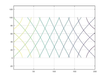
Assume a rectangular plane, flat, horizontal, and say 200 x 100 feet. An object, say the size of a walnut, is moving around on this plane. I want to be able to plot its movements in 2D on this plane. It can be a “smart” object, able to interact with any sensor to receive and send signals as needed. The speed of the “walnut” varies from 0 to a maximum of 25 miles/hr., usually moving in the range of 10 to 15 miles/hr. I would like a positional accuracy of +/- 1 cm, ideally, and a velocity accuracy of .01m/s is fine.
I have been developing a marker system that allows the “walnut” to leave a trace on the plane, but time is still not accounted for, which is critical, and would require some independent system to measure time as the walnut moves. Of course, being able to track this walnut on the plane electronically, gathering both time and location, would be a major advance over the “farmer” method of transferring the physical track into a 2D plot. So far I have struck out with any kind of light device, lasers, etc. and radio waves are so darn fast that the counters can’t keep up. I'm focusing now on sound waves and maybe even doppler sensing, since sound at 770 mi/hr is a slug compared to electromagnetic signals. My knowledge, however, compared to what folks in the sensor industry know, is tiny, and if anyone can suggest a direction that might work for me, that would be great.

Register to Reply
Pathfinder Tags: Track the Walnut
Interested in this topic? By joining CR4 you can "subscribe" to
this discussion and receive notification when new comments are added.

"Almost" Good Answers:

Check out these comments that don't yet have enough votes to be "official" good answers and, if you agree with them, vote them!
Guru

Join Date: Apr 2010
Location: About 4000 miles from the center of the earth (+/-100 mi)
Posts: 9910
Good Answers: 1141
#1

Re: electronic tracking

02/12/2019 5:32 PM
Register to Reply
Guru

Join Date: Apr 2010
Location: About 4000 miles from the center of the earth (+/-100 mi)
Posts: 9910
Good Answers: 1141
#2

Re: electronic tracking

02/12/2019 5:41 PM

It seems that you could use the same technology as is used for a computer mouse, either a roller ball or laser mouse. Capture the X and Y coordinates in a file along with a time stamp.

Register to Reply
Member

Join Date: Feb 2019
Posts: 9
#4
In reply to #2

Re: electronic tracking

02/12/2019 6:08 PM

Thanks, Rixter, for your reply. I talked to one techie in the mouse business about a year ago, and he told me it would not work at the speeds I need, and would only work with a constant relationship between the mouse, i.e. the reader, and the surface it was tracking. My walnut, unfortunately changes its relation to the plane constantly. Your other information, about the new technology bringing GPS into a world of cm accuracy does sound promising and I'll give that a good look. If GPS can do the trick, that would be the best of all worlds for me, but heretofore, such accuracy as I need was unattainable.

I want to explore sound waves as a means of distance measuring over short distances. I would still need at least three receivers so I could triangulate a position on the plane.

Register to Reply
Guru

Join Date: Apr 2010
Location: About 4000 miles from the center of the earth (+/-100 mi)
Posts: 9910
Good Answers: 1141
#12
In reply to #4

Re: electronic tracking

02/12/2019 10:22 PM

Sound waves might work. If you emit a sharp pulse periodically from your walnut and you have 4 microphones, one at each corner, then you can record the difference in arrival times at opposite corners and you can write 3 numbers into a file for each pulse: the timestamp, difference 1-3, and difference 2-4. (Note that if this is outside, any wind could affect your arrival times.)

The picture below shows the contours of arrival time differences from opposite corners. As you can see, where the contours cross defines a unique (X,Y) location for each pair of opposite microphone arrival differences.

You may need to write a computer program to convert difference pairs to (X,Y) coordinates from the file.

Register to Reply
Member

Join Date: Feb 2019
Posts: 9
#15
In reply to #12

Re: electronic tracking

02/13/2019 1:18 AM

Good thought, Rixter. I'll play with the idea and see what I can learn. One good thing is that the temperature for all electronic components will be the same, and there will be no wind (it's indoors). So if the signals are uniquely detectable through any noise, it has hope as a solution.

Register to Reply
Guru

Join Date: Apr 2010
Location: About 4000 miles from the center of the earth (+/-100 mi)
Posts: 9910
Good Answers: 1141
#24
In reply to #15

Re: electronic tracking

02/13/2019 10:13 PM

If you decide to go this route, you might want to use 40KHz ultrasonic transducers for good resolution for both the transmitting walnut and also the corner microphones. These are used for ultrasonic rangefinders and are not too hard to find.

https://www.mouser.com/Search/Refine?Keyword=ultrasonic%20transducer

I have written some Matlab code to convert the opposite corner microphone receive time offsets to XY location if you're interested.

Register to Reply
Guru

Join Date: Mar 2007
Location: by the beach in Florida
Posts: 33392
Good Answers: 1817
#3

Re: electronic tracking

02/12/2019 6:01 PM

I would use a laser or lidar tracking system....

https://www.ocularrobotics.com/products/lidar/

__________________
All living things seek to control their own destiny....this is the purpose of life
Register to Reply
Member

Join Date: Feb 2019
Posts: 9
#5
In reply to #3

Re: electronic tracking

02/12/2019 6:21 PM

Thanks, SolarEagle, for your input. My first thought to solve my problem was laser (LIDAR) technology, but alas, my walnut, as I call it, is moving erratically, and is sometimes hidden from view of any laser signal. So, the beauty and accuracy of "laser radar" was not available to me. High speed photography is also unworkable for me. I either have to draw the trace, or track, on the plane surface with a kind of inker mounted on the walnut, and then do all my math, derived from the trace, on my hands and knees with straight edges, a large protractor, and a measuring tape. It works, but is vastly more tedious than using electronic position sensing equipment (if it exists).

Register to Reply
Guru

Join Date: Mar 2007
Location: by the beach in Florida
Posts: 33392
Good Answers: 1817
#7
In reply to #5

Re: electronic tracking

02/12/2019 6:43 PM

You could have the object heat up and track it with a drone overhead using infrared, sending the signal to your laptop.....?

__________________
All living things seek to control their own destiny....this is the purpose of life
Register to Reply
Guru

Join Date: Mar 2007
Location: by the beach in Florida
Posts: 33392
Good Answers: 1817
#6
In reply to #3

Re: electronic tracking

02/12/2019 6:28 PM

__________________
All living things seek to control their own destiny....this is the purpose of life
Register to Reply
Guru
Engineering Fields - Electrical Engineering - Been there, done that. Engineering Fields - Control Engineering - New Member

Join Date: Dec 2008
Location: Long Island NY
Posts: 15600
Good Answers: 981
#8

Re: electronic tracking

02/12/2019 9:41 PM

This sounds like NHL hockey puck tracking on TV.

__________________
"Don't disturb my circles." translation of Archimedes last words
Register to Reply
Member

Join Date: Feb 2019
Posts: 9
#9
In reply to #8

Re: electronic tracking

02/12/2019 9:52 PM

Close, but no cigar, redfred: Right arena, but wrong application. Are you a hockey player, or at least a skater?

Register to Reply
Guru
Engineering Fields - Electrical Engineering - Been there, done that. Engineering Fields - Control Engineering - New Member

Join Date: Dec 2008
Location: Long Island NY
Posts: 15600
Good Answers: 981
#10
In reply to #9

Re: electronic tracking

02/12/2019 9:57 PM

I skated when I was younger but mostly using little wheels.

__________________
"Don't disturb my circles." translation of Archimedes last words
Register to Reply
Member

Join Date: Feb 2019
Posts: 9
#11
In reply to #10

Re: electronic tracking

02/12/2019 10:09 PM

Redfred, I'm reluctant to be open about the application because it may jeopardize copyrights or patents. So I'm stuck with these sterile scenarios and general descriptions. It's part of a business venture.

Register to Reply
Guru

Join Date: Mar 2007
Location: by the beach in Florida
Posts: 33392
Good Answers: 1817
#13
In reply to #9

Re: electronic tracking

02/12/2019 10:27 PM
__________________
All living things seek to control their own destiny....this is the purpose of life
Register to Reply
Member

Join Date: Feb 2019
Posts: 9
#14
In reply to #13

Re: electronic tracking

02/13/2019 1:05 AM

Thanks, SolarEagle. That patent really helped advance my knowledge and thinking on my project. I have greater hope I can actually achieve my goal. It seems that accuracy will be my greatest difficulty, but we'll see.

Register to Reply
Guru

Join Date: Oct 2006
Location: 44.56024"N 15.307971E
Posts: 8277
Good Answers: 270
#16

Re: electronic tracking

02/13/2019 3:05 AM

It sounds to me like you could adapt the circuitry used in ultrasonic liquid level measurement,the sonar type.

As you said,it will require more than one sensor and a means of triangulating the signals.

Possibly an Arduino and a few external components would do the trick.

This link may point you in the right direction,but is not an off-the-shelf fit for your application.

https://circuitdigest.com/microcontroller-projects/water-level-indicator-project-using-arduino

__________________
"A man never stands so tall as when he stoops to help a child." "Never argue with a stupid person.They will drag you down to their level and beat you with experience" "To create an apple pie from scratch, first you must create a universe"
Register to Reply
Guru

Join Date: Mar 2007
Location: by the beach in Florida
Posts: 33392
Good Answers: 1817
#17

Re: electronic tracking

02/13/2019 4:12 AM

Found this....

..."In this paper a new high resolution GPS-based system for indoor is presented. The common systems used for this purpose are not very accurate and usually expensive. The proposed approach allows to obtain systems which are both very accurate and low cost. It is based on the wideband spread spectrum technique at 24 GHz, and achieves an accuracy better than 0.5 millimeter even when the target is moving. The peculiarity of this positioning system compared to others is the fully analog correlation which improves the cost-effectiveness of the system."...

https://www.researchgate.net/publication/261197935_A_location_system_for_indoor_at_24_GHz_with_submillimeter_precision

You maybe could use this architecture with a different bandwidth for better penetration...

..."Ground Penetrating Radar, for example, is around 2.4 GHz. UWB Wall penetrating radar covers about 1.5 to 6 GHz. ( eg: High resolution ultrawideband wall penetrating radar )

However, longer wavelengths will typically get better penetration through walls -so 800 to 1000 MHz bands typically get better range for indoor coverage and are used for mobile systems."...

__________________
All living things seek to control their own destiny....this is the purpose of life
Register to Reply
Guru
Australia - Member - New Member

Join Date: Feb 2008
Location: Australia
Posts: 2181
Good Answers: 255
#18

Re: Electronic Tracking

02/13/2019 5:53 AM

Depending on your budget, the systems used for ball tracking in tennis and cricket are 3D versions of what you are wanting to do and then your positional accuracy is merely a mater of your sampling rate and known maximum velocity.

If you already have the tracking marker implemented, then a single "overhead" camera could take pics at the necessary sampling rate (like stop motion cartoons) to enable your velocity determinations.

__________________
Just an Engineer from the land down under.
Register to Reply
Guru

Join Date: Oct 2009
Posts: 1460
Good Answers: 30
#19

Re: Electronic Tracking

02/13/2019 6:10 AM

An IR transmitter at each corner of your platform casting a narrow beam which rotates to scan the appropriate 90º. The signal provides information as to beam angle and time. The receiver on the walnut aggregates the information (might need 4 separate receivers to avoid collisions).

Register to Reply
Participant

Join Date: Sep 2018
Posts: 2
#20

Re: Electronic Tracking

02/13/2019 7:58 AM

Perhaps you could embed a mems gyro and transmitter in the walnut

Register to Reply
Guru

Join Date: May 2016
Posts: 1746
Good Answers: 87
#21

Re: Electronic Tracking

02/13/2019 1:53 PM

Optical tracking seems to make the most sense.

If the item is spherical, then you could use two cameras at corners of the plate and look at the edges of the object from two angles to create a pair of intersecting vectors on the center of the object. As long as you had a stream of vectors you could identify location, time and derive direction and speed. A modification for an object of known size would be to use the edges and width of the object and derive a vector for direction and distance based on the edge angles and the width angle.

You could use one or more rotation angle encoded rotary laser scanner and a camera located at some distance from the laser to identify points and times for the position of the laser dot on the surface of the object to triangulate the position.

You could also use acoustics and have the object ping and use timing of the pulses at microphones at the corners of the plate to derive the location.

Finally, you could glue the walnut to the table and then the problem is trivial. It becomes, "You are here".

Register to Reply
Member

Join Date: Feb 2019
Posts: 9
#22

Re: Electronic Tracking

02/13/2019 3:04 PM

I'm amazed and grateful at the same time that so many of you have responded with so many hopeful approaches. I'm now feeling a bit sheepish that I have not given all of you a full understanding of what I'm trying to do. I have decided it's not fair to have you try to help me with incomplete information, and I therefore shall reveal all the necessary details.

I am an old hockey player and interested in how we skate. Many people have approached this problem with banks of cameras, etc. and have failed to perceive the simplest realities of how we skate. I have the math and physics figured out and need to validate my knowledge. I need to track the blades of both skates during skating. So I really have to track 2 "walnuts" (skate blades) at the same time. When we skate correctly, we only use one skate at a time. There is no gliding phase. Therefore, when a stroke ends and lifts off the ice, the other skate begins its power stroke. So the skates alternate time on the ice. The trace forms a "propulsion triangle", which is a right triangle and easy to make calculations upon. The actual trace is the long side of the right triangle, the short side is the projected stroke length, and the hypotenuse is the path of the body's center of mass. The vertex between the hyp and the long side is around 20 degrees and is called the angle of divergence. The pushing skate is sliding up the track on the ice defined by its angle with the hyp. We are not pushing off like a runner or like pushing of the end of the pool in a swimming turn. We are pushing sideways at about 20 degrees behind a line perpendicular to the direction of motion (it's the same angle as the angle of divergence), trying to separate our skate from our mass. This generates a forward vector.

Anyway, the trace on the ice, over time, tells you everything about a skaters stride and form, and how fast he can go. So I need any tracking system to be accurate enough to give the angle of divergence, length of long side, etc. The only tracking needed is turned on when the skate hits the ice and ends when the skate lifts off the ice. The "walnut" is the device attached to the skate blade, and as you can imagine is not in any position to be reflecting a laser beam. But it can send and receive signals of some kind.

So that should help those interested to know the difficulties of the problem and why I need accurate tracking. I will spend time on all your great suggestions over the next week, as I have time, and let you know where I end up. Finally, thank you all very much for your great efforts to help.

Register to Reply Score 1 for Good Answer
Guru

Join Date: Mar 2007
Location: by the beach in Florida
Posts: 33392
Good Answers: 1817
#23
In reply to #22

Re: Electronic Tracking

02/13/2019 4:22 PM

I would think the blade profiling has a lot to do with actual surface contact, angle of attack, force applied and resistance of ice, weight of skater, weight of skates, length of stroke, irregularities of the ice itself, temperature and other variables....Which aspects are you trying to measure?

..."When skating, different parts of the skate blade impart different properties. The front part is used for acceleration, the middle part is for speed and maneuverability and rear part is for stability. By combining several different radius's aligned at specific angles, one can optimize the performance in every area. Using these kind of templates are more for professional player/skaters. There is also a new combined template called Optimal-NC, which is using a completely new way of thinking."...

https://medium.com/@ngerasimatos/deep-dive-into-hockey-skate-profiling-27671a13e2a1

klapskates

__________________
All living things seek to control their own destiny....this is the purpose of life
Register to Reply
Member

Join Date: Feb 2019
Posts: 9
#25
In reply to #23

Re: Electronic Tracking

02/13/2019 11:25 PM

Good question, S/E. The foundation under a skater's skills is balance. Without solid balance, the moves skating requires would have you on your backside in a heartbeat. Each skater has a body shape that influences how he balances over his (or her) skates. The primary feature controlling this is the "lean" of the blade. Skates used to be built with little attention to the angle of the blade to the soul of the foot. But it makes a big difference in balance as we push. A flatter blade radius is helpful in maintaining balance, but a detriment to agility, so a radius is chosen after a skater is proficient at balance. As for different segments of the arc applying to speed or stability, I don't feel this is a good analogy. A skater doesn't magically get more speed just by skating on a different segment of the arc. Typically, the whole blade is used throughout the stroke at different stages, rocking toward the toe at the end. The force coming down your leg should generally extend straight down through the foot and the middle of the blade in a push.

Absolutely, if skates are sharpened with one edge high, the first thing you do is never let the same guy sharpen your skates again. The edges have to be level, with a hollow in between. The depth of that hollow is a skater's preference, giving you more or less grip on a curve. The actual sharpness of the edge is most important, and should be able to shave off a thin layer of fingernail run across it. There is probably a difference in friction or ease of movement along the ice resulting from the degree of "rocker", but it's not noticeable. Mostly, the ease with which a skater can balance is noticed from the forward lean "high heel effect". More "rocker" does make the skate more maneuverable, and that is noticeable. But speed is always related to leg strength and speed of reflex.

There are really two triangles involved. The "propulsion triangle", on the ice, and the "hip-skate" triangle, adjusted by the height off the ice of the hip joint and the length of an extended leg. In this triangle, the stroke is the hypotenuse, the height of the hip joint off the ice is the short side, and the long side is the projected stroke length on the ice (which is shorter than the actual extended leg).

The vector physics that creates forward propulsion is a function of the angle of divergence, length of stroke (projected on the ice), and the speed of the stroke. If the angle of divergence is narrowed (reduced), the skater will travel farther with each stroke. But if the stroke is slow, speed will still be slow. A custom rockered and forward leaning blade can increase balance and agility, but cannot influence the speed of stroke or angle of divergence. Only leg strength and fast reflexes can do that.

Thanks for bringing up the question Screaming Eagle, or rather Solar Eagle (Eagle who flies with solar cell on wings). I learned a lot myself from all the U-tube pieces on the subject.

Register to Reply
Guru

Join Date: Mar 2007
Location: by the beach in Florida
Posts: 33392
Good Answers: 1817
#26
In reply to #25

Re: Electronic Tracking

02/14/2019 1:07 AM

Who knew just skating across the ice could be so complicated....but I can't help thinking how some runners were challenged when prosthetic legs came into the picture, and how the mechanical advantage could be improved in skating with some spring loaded skates or something else that is outside the box as they say....I keep picturing hockey players with exoskeletons .....but I guess that's another thread eh?

__________________
All living things seek to control their own destiny....this is the purpose of life
Register to Reply
Register to Reply 26 comments

"Almost" Good Answers:

Check out these comments that don't yet have enough votes to be "official" good answers and, if you agree with them, vote them!
Copy to Clipboard

Users who posted comments:

HiTekRedNek (1); Jpfalt (1); Just an Engineer (1); mike bog (1); Paul Shelton (8); phph001 (1); redfred (2); Rixter (4); SolarEagle (7)

Previous in Forum: Ice Cube Relay Software Design for School   Next in Forum: Static Electrcity for Charging Batteries

Advertisement