It's always assumed that heat will flow from a hot body to a cold body and never the reverse direction without the application of external energy (i.e. a heat pump). Here is an interesting experiment in which heat does flow in the opposite direction without any external energy.
Charge a capacitor and connect a resistor. The current decays in the familiar exponential curve as current flows out of the capacitor through the resistor. Heat up a block of metal, bring it into contact with a cold piece, and monitor the temperature difference. The temperature difference decays in the exponential curve as heat flows from the hot source to the cold sink.


Add an inductor to the RC circuit and you have a RLC tank circuit. If you start with a charged capacitor, the current oscillates in a decaying sinusoid waveform. If there were "heat inductor", heat could flow in a decaying exponential with alternating swings moving heat from the "cold" sink to the "hot" source.


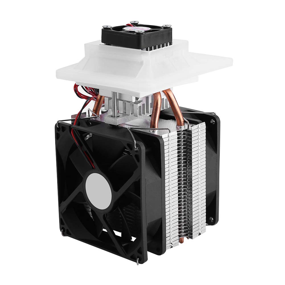
A "heat inductor" was constructed using a Peltier device. A Peltier device is a series of P and N type semiconductors connected between two heat conducting but electrically insulating plates. The arrangement is such that the P and N are arranged to be parallel for heat flow but connected in series electrically. Heat is carried from one plate to the other by the electrons and holes which flow in the N and P material.

When voltage is applied, heat moves with the electrical current. When a temperature differential is applied, electrical current moves with the heat. In either case, flow of heat and flow of electrical current are connected. Placing an inductor in the electrical circuit is equivalent to creating a "heat inductor" in the thermal circuit.
The Peltier device shorted by an inductor is placed between heated copper and cold copper and the heat capacity of the hot copper (capacitance) conducted through the Peltier/inductor (resistance and inductance) creates a thermal tank circuit.

"Fig. 2Equivalent electrical network and illustration of the heat flow within the considered thermal connection between a body with heat capacity C at temperature Tb and another body or a thermal reservoir at Tr.
(A) The electrical network consists of a Peltier element (Π) with internal resistance R and thermal conductance k in a closed circuit with an ideal inductance L. The oscillatory current I is ultimately driven by the voltages supplied by the thermoelectric effect due to the temperature difference between the cold and the hot end of the Peltier element, and the induced voltage LI.across L (see Eq. 1A). (B) Sketch of the individual contributions to the flow of heat (open arrowheads, arrow lengths not to scale) in Eqs. 1B and 1C for situations when heat is flowing from (filled light/yellow arrows) or to (filled dark/purple arrows) the warmer end of the Peltier element, drawn for one oscillation cycle of Tb(t), as depicted in Fig. 1 (B and D). The thermal oscillator acts during a full period of an oscillation cycle of Tb(t) alternately as a thermoelectric generator (i), a cooler (ii), a generator (iii), and a thermoelectric heater (iv). During all these processes, a small amount of electromagnetic power (LII., green double arrows) is exchanged with the inductor, although the total stored magnetic energy is always less than a fraction Δ0/Tr of the initially deposited excess heat ~ CΔ0 (see text and Fig. 5). "

"Fig. 3Evolution of the temperature difference between a cooling body and a thermal bath or another finite body, which are connected in an experiment using a thermal inductor.
(A) Normalized temperature difference (Tb(t) − Tr)/Δ0 between a finite body and a thermal reservoir for L = L* = RC/k and ZT between 0.25 (red) and 5 (blue) in steps of 0.25, obtained from solving Eq. 3. The time is in units of τ* = C/k. The black line represents a corresponding relaxation process with a time constant τ*, which would take place if the Peltier circuit were interrupted from the beginning. If the thermal connection is not removed after reaching the respective Tb,min (dashed line), Tb(t) approaches thermal equilibrium with eventually Tb = Tr in all cases. The inset shows the damped oscillations of both Tb(t) and I(t). (B) Temperatures Tb(t) and Tr(t) of two connected finite bodies with equal heat capacities, relative to the mean initial temperature T¯¯¯=[Tb(0)+Tr(0)]/2 and normalized to the initial temperature difference Δ0, for ZT = 5 (time in units of τ*). Tav denotes their average value showing local minima around Tb ≈ Tr (the numbers for Tav were calculated for Δ0/Tr = 0.27). The inset shows the evolution of the total entropy gain as a function of time in corresponding normalized units."
https://www.sciencedaily.com/releases/2019/04/190419165531.htm
https://advances.sciencemag.org/content/5/4/eaat9953


 Re: Thermodynamic magic enables cooling without energy consumption


"Almost" Good Answers: