
Interested in this topic? By joining CR4 you can "subscribe" to
this discussion and receive notification when new comments are added.
Copy to Clipboard
Users who posted comments:34point5 (2); Andy Germany (4); hydrogenhead (14); LAA_Lucke (6); rhkramer (2); tcmtech (4); Tobugrynbak (1); TonyS (1)
Advertisement
|
Advertisement
|
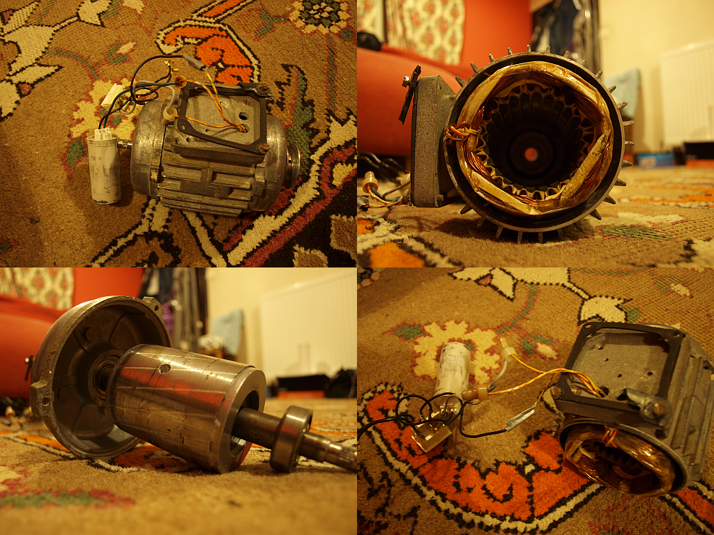

 Re: Small induction motor generator project


