I have got this rotating rectifier for the rotor of the synchronous motor and this circuit needs to be tested.
I have two questions how does it work especially how the Zener diode work in this circuit and how do I find the avalanche voltage for these diodes - I looked in the data sheet and it seems the avalanche will occur at 200 Volts.
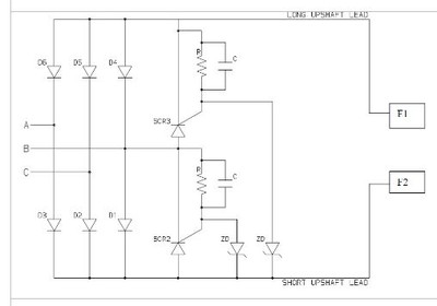
Another question is this circuit the two SCR are they for protection to sort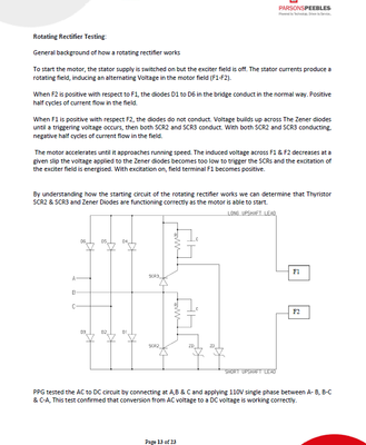
 the field when it gets above some voltage or it helps during the startup
for better quality pics
https://we.tl/t-AA1E6XSng7


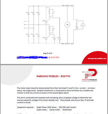
 Re: Syncronous motor Rotating rectifier


"Almost" Good Answers: