Previous in Forum: Earth Pit Distance   Next in Forum: Does the Newly Purchased Chip Need to be Programmed?
Close
Close
Close
73 comments
Active Contributor

Join Date: Jul 2010
Location: Dallas Suburb
Posts: 23
Good Answers: 2

Current Sensor

09/07/2021 9:02 AM

NEWBY ALERT!!!!

I have spent several hours doing G**le searches and reading various documents and have come to the conclusion that I know nothing! I don't even know the correct questions to ask! So, perhaps, a statement of the problem and associated requirements might allow someone to send me off in the correct direction.

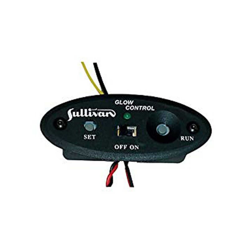
I need to buy/build/whatever a current sensor with some strange requirements. The application is a "yes/no" indicator on a battery pack used to power the glow plug of a model airplane engine. I don't need to know how much current is being drawn, only that the glow plug is operating and not burned out.

1. Small. The size of my thumb from the first knuckle on.

2. Voltage available: 2.4 - a couple of 1.2V NiMh in series.

3. Current flow will be zero when the glow plug is either not attached, or burned out. A typical current draw when operating normally will be otoo 2-5 amps

4. Indication must be visual in bright sunlight.

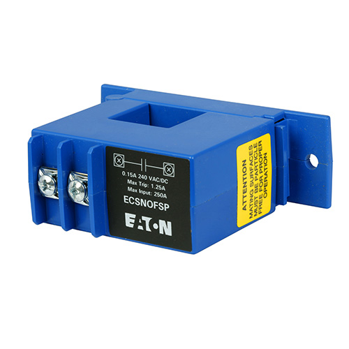
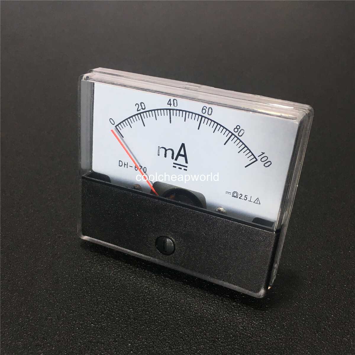
5. Direct or indirect sensing? Intuition says I don't want the current powering the glow plug passing through the sensor as you would if you used, say, an inline ammeter.

Can anybody give me some insight?

Thanks.

Regards,

Bill Lee

__________________
BillLee
Register to Reply
Pathfinder Tags: current sensing
Interested in this topic? By joining CR4 you can "subscribe" to
this discussion and receive notification when new comments are added.

Comments rated to be Good Answers:

These comments received enough positive ratings to make them "good answers".

Comments rated to be "almost" Good Answers:

Check out these comments that don't yet have enough votes to be "official" good answers and, if you agree with them, rate them!
Guru

Join Date: Apr 2010
Location: About 4000 miles from the center of the earth (+/-100 mi)
Posts: 9725
Good Answers: 1118
#1

Re: Current Sensor

09/07/2021 9:30 AM

You can get a clamp-on ammeter that reads DC current. You don't have to wire it into the circuit, but it would be bigger than your thumb...

  • Be sure to get one that reads DC current. Some only read AC current.

Digital Clamp Meter Mini AC DC Current Tester Resistance Voltage Detection Multimeter, UT210B - Walmart.com

Register to Reply
Guru

Join Date: Apr 2010
Location: About 4000 miles from the center of the earth (+/-100 mi)
Posts: 9725
Good Answers: 1118
#2

Re: Current Sensor

09/07/2021 10:28 AM

If you want to experiment a little bit, get a small compass and put it on top of the wire. When there is current flowing in the wire, the needle should turn to a right angle to the wire.

Oersted's Compass - MagLab (nationalmaglab.org)

Register to Reply Score 1 for Good Answer
Guru

Join Date: Mar 2007
Location: by the beach in Florida
Posts: 33233
Good Answers: 1807
#3

Re: Current Sensor

09/07/2021 10:57 AM
__________________
All living things seek to control their own destiny....this is the purpose of life
Register to Reply
Active Contributor

Join Date: Jul 2010
Location: Dallas Suburb
Posts: 23
Good Answers: 2
#4

Re: Current Sensor

09/07/2021 11:45 AM

Thanks for the comments.....

I need to expand my requirements.

My intent is to build a battery case using either 2 NiMh C-cells or 4 AA cells. The unit needs to be small enough to strap on my arm with the battery leads to the glow plug attached. I need the form to be as light as possible and as thin as possible (hence, the battery size(s)). I need to be able to see at a quick(!) glance if the plug is working when I attach the battery leads to it. I.e., only a yes/no indication where yes == LED ON would mean "plug is o.k.", lack of LED ON would mean open circuit and plug failure.

This rules out the available external units, such as were identified above, and leads me to the need to build the unit myself.I envision a long cylinder approximately the same diameter as the battery I choose to use with the sensor and associated LED on the tip where the battery wires could attach. Add in a small pot to allow me to adjust the voltage to the plug.

My problem is I am not a EE and need guidance.

Thanks.
Bill Lee

__________________
BillLee
Register to Reply
Guru
United Kingdom - Member - Indeterminate Engineering Fields - Control Engineering - New Member

Join Date: Jan 2007
Location: In the bothy, 7 chains down the line from Dodman's Lane level crossing, in the nation formerly known as Great Britain. Kettle's on.
Posts: 32049
Good Answers: 838
#5

Re: Current Sensor

09/07/2021 1:19 PM

If it’s a <…glow plug…> then an optical, rather than electronic, technique would be better.

However, a scattering of components can indicate the dip in battery volts when current is being drawn.

Someone else can actually design the thing.

__________________
"Did you get my e-mail?" - "The biggest problem in communication is the illusion that it has taken place" - George Bernard Shaw, 1856
Register to Reply
Guru

Join Date: Jul 2008
Posts: 1681
Good Answers: 144
#6

Re: Current Sensor

09/07/2021 4:31 PM

You might be a little quick to dismiss something "in line".

You gave operating values of 2.5V and between 2A & 5A. A little Ohm's law and napkin precision math gives us a glow plug resistance between 0.5 and 1.0 ohms.

Sources such a Digikey and Mouser have hundreds of low value resistors. The Ohmite# 630HR010E is a 0.010 ohm through hole example part. Our napkin math puts this at between 2% and 1% of the glow plug resistance. Having this in series should not cause a human observable drop in performance.

Napkin math on 0.010 ohms and 2A thru 5A gives us 0.020V thru 0.050V. I'm not going to take the time to read the data sheets but I suspect a low cost LM311 voltage comparator will work with this. A little bit of RC filtering, and ESD suppression and you should have one output for no current and another output for current over your threshold (possibly 1A).

A pot might be desired to deal with chip to chip input offset variations but "select at test" would allow fixed value resistors to be used by "trial and error" method.

Digikey, Mouser and others have many displays. Sunlight readable makes selection more difficult but there are many available.

I doubt that the LM311 will work on your 2.4V (I'm not looking it up). If a "meter battery" is acceptable then this should provide a candidate path forward. If not then this is still a valid idea but component selection will be a bit more challenging.

If you get it to work then please come back, post pictures and tell us how it went.

__________________
Few things limit our potential as much as knowing answers and setting aside questions.
Register to Reply Score 1 for Good Answer
Guru

Join Date: Sep 2009
Posts: 1056
Good Answers: 88
#7

Re: Current Sensor

09/07/2021 4:55 PM

If you're into electronics it would not be that difficult to get a small ferromagnetic toroid core, cut a small gap with a dremel-type tool and diamond disc, wide enough to stuck a small hall sensor there (preferably a linear one like A1302 or something equivalent to have control on sensitivity, threshhold etc) and epoxy it back solid. This will sense current on a cable that runs through the torroid and the need for a shunt resistor to sense the current is elliminated. But then in both cases you need a second power source for driving the hall sensor, the led output and possibly an op-amp for any other voodoo neded like increasing sensitivity etc.There are other shortcuts like pasing tha cable more than once in the torroid ie making it effectively a "coil". Also there are ready-made solutions like ACS712 that handles 5A (there are 20 and 30A versions), needs external 5V will drive a led directly (can sink 10mA) but will not survive high current shorts S.M.

__________________
Life is complex. It has a real part and an imaginary part.
Register to Reply
6
Guru

Join Date: Apr 2010
Location: About 4000 miles from the center of the earth (+/-100 mi)
Posts: 9725
Good Answers: 1118
#8

Re: Current Sensor

09/07/2021 6:16 PM

You could wind some turns of your supply to the glow plug around a reed switch to make your own reed relay. The contacts could be in a battery - resistor - reed relay - LED circuit. The magnetic field from the current would cause the contacts to attract each other turning on the LED when glow plug current was present.

Note: Magnetic field to be supplied by current through coil around reed switch rather than moving magnet.

You would have to experiment to see how many turns would close the relay when the glow plug current flows. (With 2-5 amps glow plug current, it shouldn't take too many.)

Register to Reply Good Answer (Score 6)
Guru

Join Date: May 2006
Location: Placerville, CA (38° 45N, 120° 47'W)
Posts: 6178
Good Answers: 247
#12
In reply to #8

Re: Current Sensor

09/08/2021 12:24 AM

Excellent idea! Since the OP is clearly a relatively new learner in this field, a complete circuit diagram would be appropriate.

If you can't produce one, perhaps I could...

__________________
Teaching is a great experience, but there is no better teacher than experience.
Register to Reply
4
Guru

Join Date: Apr 2010
Location: About 4000 miles from the center of the earth (+/-100 mi)
Posts: 9725
Good Answers: 1118
#17
In reply to #12

Re: Current Sensor

09/08/2021 10:27 AM

Not too artistic, but here is sort of what I had in mind:

You can use the same batteries as the glow plug. The LED circuit should only take about 20 milliamps with a 120-ohm resistor. Mind the polarity on the LED. Coil just one of your 2 leads around the reed switch, as closely as possible.

Amazon.com: Gebildet 20pcs Reed Switch Reed Contact Normally Open (N/O) Magnetic Induction Switch (2mm14mm) : Industrial & Scientific

Register to Reply Good Answer (Score 4)
Active Contributor

Join Date: Jul 2010
Location: Dallas Suburb
Posts: 23
Good Answers: 2
#19
In reply to #17

Re: Current Sensor

09/08/2021 11:18 AM

That is so simple! I dabbled a bit with a breadboard and some LEDs, but I certainly had the idea that it would be far more complex than this! I'll give that a try.

Thanks.

Bill Lee

__________________
BillLee
Register to Reply Score 1 for Good Answer
Guru

Join Date: May 2006
Location: Placerville, CA (38° 45N, 120° 47'W)
Posts: 6178
Good Answers: 247
#22
In reply to #19

Re: Current Sensor

09/08/2021 4:33 PM

To Bill, and anyone else interested.

In case you aren't familiar with reed switches, they are glass tubes that have two or more electrodes in the general shape of a reed. In the absence of magnetic fields, the two reeds do not make contact. A sufficiently strong magnetic field of the correct orientation makes the two reeds attract each other, closing an electric circuit. here are a few:

The red lines in the background have a 1/4" spacing, to show the sizes. Here is a closeup of the contacts of one, with no magnet:

You can see a tiny gap between the tips of the two reeds. bring a magnet near, with the correct pole orientation, and that gap disappears:

This particular magnet has its poles on the flat faces (towards and away from the glass). On this particular reed switch, it does not matter whether the closer pole is N or S. These aren't the clearest of photos, but I think the concept can be seen...

__________________
Teaching is a great experience, but there is no better teacher than experience.
Register to Reply Score 1 for Good Answer
Guru

Join Date: Oct 2006
Location: 44.56024"N 15.307971E
Posts: 7806
Good Answers: 264
#59
In reply to #22

Re: Current Sensor

09/12/2021 4:54 AM

I had a contract to install over 1500 reed switches and magnets on machines to monitor camshaft revolutions.

(This was long ago,before there were hall effect and modern digital methods).

They never failed except from physical damage.

They had a built in resistor to limit current,and to distinguish normal operation from a short circuit by the owner-designed computer monitoring system.

Multi-millions of operations,Zero failures.

They are very reliable in a properly designed circuit.

__________________
"A man never stands so tall as when he stoops to help a child." "Never argue with a stupid person.They will drag you down to their level and beat you with experience" "Homo homini lupus"
Register to Reply Off Topic (Score 5)
Guru

Join Date: May 2006
Location: Placerville, CA (38° 45N, 120° 47'W)
Posts: 6178
Good Answers: 247
#63
In reply to #59

Re: Current Sensor

09/12/2021 11:12 AM

Good to know. Thanks.

__________________
Teaching is a great experience, but there is no better teacher than experience.
Register to Reply Off Topic (Score 5)
Guru

Join Date: May 2006
Location: Placerville, CA (38° 45N, 120° 47'W)
Posts: 6178
Good Answers: 247
#23
In reply to #19

Re: Current Sensor

09/08/2021 6:48 PM

Here's my version of Rixter's excellent suggestion:

This is identical to his original circuit, except that I've added a Normally Open button switch. Press that button to heat the glo plug and simultaneously test. Note that the LED will ONLY glow if the glo plug is heating. if the glo plug is burned out (bad, open), there will be no current to activate the reed switch. It's not likely that a glo plug would get shorted, but if somehow the plug were shorted, it would draw so much current that the battery voltage would drop below that required for the LED to illuminate. If a very large battery were used in such a case, the shorted plug would be indcated by the emission of the magic smoke, somewhere!

I have not yet experimented with the size of wire or the number of turns required. The wire would presumably be enameled solid "magnet wire" of a size somewhere in the range of AWG 20-30. Anything smaller than #30 would not be able to carry the 2 Amp current specified.

There do exist reed switches with coils already mounted, but the one I happen to have on hand has a coil resistance of 1000Ω. That means it is activated by vastly lower current.

The direction of winding the coils does not matter, at least on the one I tried.

__________________
Teaching is a great experience, but there is no better teacher than experience.
Register to Reply Score 1 for Good Answer
Guru

Join Date: Apr 2010
Location: About 4000 miles from the center of the earth (+/-100 mi)
Posts: 9725
Good Answers: 1118
#42
In reply to #23

Re: Current Sensor

09/09/2021 7:07 PM

Much better than my drawing! Thanks.

Register to Reply
Guru

Join Date: Oct 2006
Location: 44.56024"N 15.307971E
Posts: 7806
Good Answers: 264
#31
In reply to #17

Re: Current Sensor

09/09/2021 7:32 AM

Very good.As simple as it gets,with least number of components.

__________________
"A man never stands so tall as when he stoops to help a child." "Never argue with a stupid person.They will drag you down to their level and beat you with experience" "Homo homini lupus"
Register to Reply
Guru

Join Date: Apr 2009
Location: USA, Florida
Posts: 1587
Good Answers: 125
#71
In reply to #8

Re: Current Sensor

09/15/2021 2:05 PM

That is ridiculously simple.

Wanna work on a Tokomak project I've been hearing about...?

__________________
An obstacle is something you see when you take your eyes off the goal.
Register to Reply
Guru

Join Date: Oct 2006
Location: 44.56024"N 15.307971E
Posts: 7806
Good Answers: 264
#9

Re: Current Sensor

09/07/2021 7:54 PM

All you really need is a continuity tester,like a led in series with a normally open push button.

If the glow plug has continuity,it is good,or shorted.

Push to test.

If the glow plug is good,the led comes on.

If it is shorted,the LED will be much brighter.

If it does not come on,it is a bad (open) glow plug.

Recess the LED in the tube you use to house your batteries,so it can be seen in bright sunlight.

A miniature push button can also be mounted on your battery tube.

You might consider using a flashlight that has two cells of the same size that you plan to use as a carrier for your batteries.You might also use the switch.

LED's and Push buttons are cheap and readily available.

Look for these on Google:CYT1092

Amazon also has a large assortment of LED's of many colors and sizes.

For a 20 milliamp RED LED you will need approximately 120 ohm resistor between your 2.4 volt power supply and the LED and your 2.4 volt power supply.

The cold resistance of the glow plug will affect the resistor value.

__________________
"A man never stands so tall as when he stoops to help a child." "Never argue with a stupid person.They will drag you down to their level and beat you with experience" "Homo homini lupus"
Register to Reply
Guru

Join Date: Oct 2006
Location: 44.56024"N 15.307971E
Posts: 7806
Good Answers: 264
#16
In reply to #9

Re: Current Sensor

09/08/2021 6:56 AM

The circuit above is passive;it requires no power except when the test button is pressed.

No burden on the batteries.

__________________
"A man never stands so tall as when he stoops to help a child." "Never argue with a stupid person.They will drag you down to their level and beat you with experience" "Homo homini lupus"
Register to Reply
Guru

Join Date: Mar 2011
Location: Sebastopol, California
Posts: 1145
Good Answers: 50
#18
In reply to #9

Re: Current Sensor

09/08/2021 10:32 AM

I like this idea. It is similar to the arm/fire circuit for launching rockets. You have a load (lamp) in series with the igniter wire that lights with continuity and a button to press that shorts the load and sends full voltage to the igniter wire. If no light when armed then the igniter is bad.

__________________
Most people are mostly good most of the time.
Register to Reply
Guru
Hobbies - DIY Welding - Wannabeabettawelda

Join Date: May 2007
Location: Annapolis, Maryland
Posts: 7860
Good Answers: 452
#10

Re: Current Sensor

09/07/2021 11:49 PM

At the risk of over-engineering a solution, a hall effect current sensor of the type offered by Allegro Microsystems might do the trick. These devices output a voltage that is proportional to the current flowing through the device. What you would want to do is have the device go into the input of a comparator that drives a bright LED. If the output voltage is greater than about a half volt, (the reference voltage to the comparator) then the LED lights. That way you can avoid false triggers due to stray magnetic fields or the noise floor of the comparator.

A five amp sensor from Allegro is the ACS70331. It works with low supply voltage (3 -4.5) This chip outputs 400 mV per amp meaning at two amps the output voltage will be about 0.8 V. The 10K to 100K divider will give you a 'reference voltage' of about 0.4 V so as long as there is about one amp or greater, the comparator should trip and allow current to be pulled down through the LED. This comparator is rated for 10 mA output current which should be enough current to light most LED's.

https://www.allegromicro.com/-/media/files/datasheets/acs70331-datasheet.ashx

The 8-pin SOIC is probably easier to work with than the QFN package.

Currently out of stock. Chip shortages you know.

https://www.digikey.com/en/products/detail/allegro-microsystems/ACS70331EOLCTR-005U3/9674759?s=N4IgTCBcDaIIIGEDKB2ADAZgwRgKIHkAZBAFQCUBaNNAVgFUMQBdAXyA

Comparator

https://www.digikey.com/en/products/detail/texas-instruments/TLV3401CD/1669345

You can have orders shipped via first class mail from DigiKey for about $5 if the order is less than 13 oz.

Register to Reply
Guru
Hobbies - DIY Welding - Wannabeabettawelda

Join Date: May 2007
Location: Annapolis, Maryland
Posts: 7860
Good Answers: 452
#11
In reply to #10

Re: Current Sensor

09/08/2021 12:10 AM

P.S. The resistance of the current sensor is about 0.001 ohms so you only lose about 1 mV for every amp flowing through it. Typically, you will have higher ohmic losses just due to the wiring and connections in your circuits. You will need at least three Ni-Cad's to run this kind of circuit. I'd be using three D-cells and add some in-line resistance to the glo-plug if you need to limit the current due to the higher voltage. You might need to change the 300 ohm resistor to a lower value if you need the LED to be brighter especially if you are using 1.2 V Ni-Cads. I don't think you will be able to do much with just two Ni-Cads unless you are willing to add a boost stage to get the voltage up to where you can work with it. A third cell is much easier than a boost converter.

Good luck with your quest.

Register to Reply
Guru
Philippines - Member - New Member Engineering Fields - Instrumentation Engineering - New Member Engineering Fields - Control Engineering - Who am I?

Join Date: Oct 2006
Location: Northern Mindanao, Philippines
Posts: 2127
Good Answers: 51
#13

Re: Current Sensor

09/08/2021 2:21 AM

There are current limit switches available. This one is AC but I think there are DC models as well. You set the current that the switch will change position and off you go. Search current limit switch.

__________________
Miscommunication: when what people heard you say differs from what you said. Make yourself understood.
Register to Reply
Guru

Join Date: Mar 2007
Location: by the beach in Florida
Posts: 33233
Good Answers: 1807
#14

Re: Current Sensor

09/08/2021 2:43 AM

Seems to me you could just use a thermistor to sense the cylinder temp, if the temperature drops, the glow plug has failed, and activates an LED....

__________________
All living things seek to control their own destiny....this is the purpose of life
Register to Reply
Guru

Join Date: Mar 2007
Location: by the beach in Florida
Posts: 33233
Good Answers: 1807
#15
In reply to #14

Re: Current Sensor

09/08/2021 5:39 AM

No spamming allowed....cease and desist...Praise and adoration is ok...

__________________
All living things seek to control their own destiny....this is the purpose of life
Register to Reply
Power-User

Join Date: Jan 2009
Posts: 227
Good Answers: 11
#25
In reply to #14

Re: Current Sensor

09/08/2021 9:55 PM

You're on to something there. The thermistor could also be used to determine when the glow plug is hot enough for starting the engine.

Register to Reply
Guru

Join Date: May 2006
Location: Placerville, CA (38° 45N, 120° 47'W)
Posts: 6178
Good Answers: 247
#26
In reply to #25

Re: Current Sensor

09/08/2021 11:15 PM

The problem here is the time delay Due to the small mass of the glow element, the much larger mass of the glow plug stem, and the vastly larger mass of the engine housing, I suspect that it would take quite a few seconds for the thermistor to react to the heat of the glow element.

Rixter's solution would be almost instantaneous. With some experimentation, the number of turns of wire in the solenoid activating the reed switch could conceivably be adjusted so the LED would illuminate when the glow plug is first connected, and then go out when the glow plug is hot, since the resistance of the glow element increases significantly with temperature. As is the case with tungsten light bulbs, the initial current is very high, but as the element heats up, the resistance goes up, so the current goes down.

__________________
Teaching is a great experience, but there is no better teacher than experience.
Register to Reply
Guru

Join Date: Mar 2007
Location: by the beach in Florida
Posts: 33233
Good Answers: 1807
#27
In reply to #26

Re: Current Sensor

09/09/2021 1:30 AM

I'm not sure that the reed switch would stand up to the vibration likely to be present...we'll see

__________________
All living things seek to control their own destiny....this is the purpose of life
Register to Reply
Guru

Join Date: May 2006
Location: Placerville, CA (38° 45N, 120° 47'W)
Posts: 6178
Good Answers: 247
#28
In reply to #27

Re: Current Sensor

09/09/2021 1:57 AM

I've been assuming that the connection from the circuit to the glow plug would be via flexible stranded wire, which would be disconnected once the engine has started. Virtually no engine vibration should reach the circuit, including the reed switch and its winding.

__________________
Teaching is a great experience, but there is no better teacher than experience.
Register to Reply
Guru

Join Date: Mar 2007
Location: by the beach in Florida
Posts: 33233
Good Answers: 1807
#29
In reply to #28

Re: Current Sensor

09/09/2021 6:05 AM

Well if that's the case, then a simple continuity tester is all that is needed...

__________________
All living things seek to control their own destiny....this is the purpose of life
Register to Reply
Associate

Join Date: Aug 2014
Posts: 33
Good Answers: 2
#20

Re: Current Sensor

09/08/2021 12:29 PM

Simplest solution might be;

4x, 5 amp silicon diodes in series with the glow plug supply would reduce the glow plug supply voltage by approximately 2.8V. If this is ok;

2.8V is more than enough to light an led. A red led can light with as little as 2.1V.

2.8V-2.1V=0.7V led current is 0.02A 0.7/0.02=35 ohms

So place the red led with a 33 to 50 ohm resistor in series with it across the 4 diodes and it will light when there is current flow only.

The resistor can be 1/8 or 1/4 watt.

-|--D---D---D---D--|-

-|--LED---Resistor--|-

Polarity is important.

The silicon diodes will dissipate about I x 2.8V watts, I would cover them in epoxy and keep them away from anything that does not like heat but not right on the motor either.

Try 3 silicon diodes and no resistor, may be fine.

Register to Reply
Guru
Hobbies - DIY Welding - Wannabeabettawelda

Join Date: May 2007
Location: Annapolis, Maryland
Posts: 7860
Good Answers: 452
#21
In reply to #20

Re: Current Sensor

09/08/2021 1:24 PM

I think you always want some series resistance with the diode to help limit current. It's hard to count on current sharing as the die temperatures change of the LED and series string of PN diodes in parallel with the LED. The forward drop voltage across a PN diode can change fairly significantly as a function of die temp. From junction temperature of 25 C to 150 C, the voltage drops by almost 0.2 volts. At first application of power, the voltage might be too high for the LED to survive without some dropping resistance. The chart below is for a Vishay EGP51G-E3/C PN diode.

Register to Reply
Associate

Join Date: Aug 2014
Posts: 33
Good Answers: 2
#24
In reply to #20

Re: Current Sensor

09/08/2021 7:49 PM

Should have read the whole quest!

Register to Reply
Guru

Join Date: Mar 2007
Location: by the beach in Florida
Posts: 33233
Good Answers: 1807
#30

Re: Current Sensor

09/09/2021 6:34 AM

__________________
All living things seek to control their own destiny....this is the purpose of life
Register to Reply
Guru

Join Date: May 2006
Location: Placerville, CA (38° 45N, 120° 47'W)
Posts: 6178
Good Answers: 247
#33
In reply to #30

Re: Current Sensor

09/09/2021 11:27 AM

I hate videos that talk about stuff, but don't show it in action! It's been many years since I gave away my little engine, so I could be mistaken, but as I recall, the glow plug is only powered to start the engine. Once the engine has started, the wires are disconnected, and the burning fuel keeps the glow element hot enough to continue igniting the next charge of fuel, in effectively a modified diesel configuration.

Bill did a good job of explaining his needs in post#32. He needs speed! Since the wires will be disconnected except while the engine is started, there is no need for the switch I had in the previous circuit; simply connecting the wires to the glow plug via some sort of quick connect/disconnect will heat the glow plug and activate the reed switch and LED. Once the wires are disconnected from the glow plug, there will be no current flowing anywhere:

__________________
Teaching is a great experience, but there is no better teacher than experience.
Register to Reply Score 1 for Good Answer
Guru

Join Date: Mar 2007
Location: by the beach in Florida
Posts: 33233
Good Answers: 1807
#34
In reply to #33

Re: Current Sensor

09/09/2021 12:30 PM

Well some leave the plug wired and there's a module that just press fits into a receiver type plug that facilitates contact to the glo-plug and ground that checks continuity and supplies voltage to the glow plug with the press of a button...and also runs a starter motor I think...

__________________
All living things seek to control their own destiny....this is the purpose of life
Register to Reply
Guru

Join Date: May 2006
Location: Placerville, CA (38° 45N, 120° 47'W)
Posts: 6178
Good Answers: 247
#70
In reply to #33

Re: Current Sensor

09/15/2021 1:13 AM

I finally got a coil wound and a prototype set up. IT WORKS! (Rixter's original concept). With a coil consisting of a single layer with 22 turns of #23 wire, The reed switch closes and the LED illuminates with 2 Amperes of current, but the switch does not close, so of course the LED stays off, with 1 Ampere of current.

I have lots more experimenting to do, but so far, I have not gotten the LED to come on when the filament is cold and go out when the filament heats up.

I'll have more info and a photo or two, hopefully tomorrow.

__________________
Teaching is a great experience, but there is no better teacher than experience.
Register to Reply
Active Contributor

Join Date: Jul 2010
Location: Dallas Suburb
Posts: 23
Good Answers: 2
#32

Re: Current Sensor

09/09/2021 9:44 AM

The responses have been great! Thanks!

A bit more of the environment I am in that I hope will explain my requirements a bit more fully and will show why some of the (good!) suggestions here are not applicable.

I am an old guy, 79yo, and have been flying model airplanes since I was a (very) little kid. My specialty is Control Line Racing, where two or three models are being flown simultaneously, against each other and against the clock. As is usual in almost all racing events, you start quickly, go fast, pause for pit stops, etc.

Control Line racing is a team event in that you have a pilot who actually flies the model, and a pit crew (one or two people) that services the model on the ground. A race will be a certain number of laps and includes necessary pit stops.

I don't actually fly the model, I am a pit man. I must be able to start the model quickly at the beginning of the race, then launch it.When the model is stopped during the race, I must retrieve it, refuel it, and restart the engine, all as fast as possible. With several variations, this involves attaching the battery to the glow plug where I must be able to determine if it is still working, all as rapidly as possible. At the time, I don't care how much current is being used, only a yes/no indication.

Historically I have used a commercially available battery unit, a GloBee FirePlug, about the size and weight of the large cylindrical 1-1/2v dry cell. The unit includes a pot to control the amount of current to the plug, and an inductance amp meter. It uses an X-cell, 5ah 2v SLA battery. In order to have the battery and the clip for the glow plug handy during a fast pit stop, I strap the unit to my arm. This has worked well and still does but has some disadvantages I am trying to overcome with the the content of this thread.

1. The GloBee is heavy with the SLA battery.

2. The round cylindrical form is not conducive to strapping to your arm. Coupled with the weight, it must be strapped securely or it will flop around and come loose. It becomes very uncomfortable after a while when strapped down tight enough to remain secure.

3. The inductance amp meter indicates the plug is good or not, but requires more than "just a glance" to ascertain.

4. The battery, while available, is not READILY available, and is expensive, running usually over $25 a piece. And did I say: heavy?

5. The GloBee is no longer produced and has not been for many years. Parts are not available from the manufacturer (Fusite in Cincinnati), and the manufacturer will not respond to requests for information. E.g., the inductance amp meter plastic case will break if the unit get bumped in the right way, and I can NOT find a replacement for that meter anywhere on the 'net!

Hence the thrust of this thread.

Again, thanks for all of the feedback.

Regards,

Bill Lee

__________________
BillLee
Register to Reply
Guru

Join Date: Mar 2007
Location: by the beach in Florida
Posts: 33233
Good Answers: 1807
#35
In reply to #32

Re: Current Sensor

09/09/2021 1:30 PM

I would carry the battery in a fanny pack, and lengthen the leads , attach the ammeter to your arm with continuity LED attached...

__________________
All living things seek to control their own destiny....this is the purpose of life
Register to Reply Score 1 for Good Answer
Power-User

Join Date: Jan 2009
Posts: 227
Good Answers: 11
#36
In reply to #35

Re: Current Sensor

09/09/2021 3:29 PM

This is a good idea; if you go to a fanny pack, you can use any convenient battery of the same voltage and same or greater amp-hour rating. The weight limit becomes what you can tolerate hanging around your waist. Remove the battery from the case of the GloBee and replace it with a cable that runs up your sleeve, then down to your fanny pack. Use at least 18-gauge wire (lamp cord?) for durability as well as low conduction loss and minimal heating - you don't want to scorch your armpit! Now you can retain the convenient arm mount without the weight. This also gives you space in the case for one of the quick indicator ideas given here; if you're going to a fanny pack battery, you can add another pair of wires to the battery cable for a second higher voltage battery to drive indicator/test electronics if needed. If those are sleeved with the glow plug battery, they can be smaller and lighter.

Register to Reply
Guru

Join Date: Mar 2007
Location: by the beach in Florida
Posts: 33233
Good Answers: 1807
#60
In reply to #36

Re: Current Sensor

09/12/2021 6:38 AM

__________________
All living things seek to control their own destiny....this is the purpose of life
Register to Reply
2
Guru

Join Date: May 2006
Location: Placerville, CA (38° 45N, 120° 47'W)
Posts: 6178
Good Answers: 247
#37
In reply to #32

Re: Current Sensor

09/09/2021 3:56 PM

I've been thinking about this quite a bit, and have now modified my drawing one more time:

Apparently, current glow plugs use Platinum wires as heating elements. All metals, including Platinum, have electrical resistance, and that resistance increases with temperature. Increasing resistance means decreasing current. When you first connect a battery to the glow plug, its heating element is at ambient temperature, so has its lowest resistance and highest current when connected to a battery. When the filament heats up its resistance increases, so the current goes down.

At the ≈1500° F hot temperature of a glow plug, its resistance will be roughly triple its ambient temperature resistance, so the current will be roughly 1/3 of the initial current. Thus it should be relatively easy to find a number of turns of the coil that will close the reed switch when first connected, but allow it to open once the glow plug is hot. At that point the first LED will go out, but the user would not know the difference between a hot filament and one that had just burned out.

The second reed switch would have two or three times the number of turns of wire, so its magnetic field would be strong enough to keep its switch closed at the hot current level. Thus both LEDs would come on at first; when the filament got hot, the first LED would go out, but the second would remain lit, indicating continued current and a good glow filament.

I've suggested using orange and red LEDs, which require lower voltages, while green, blue, and white LEDs require higher voltages and might not work with some battery configurations.

__________________
Teaching is a great experience, but there is no better teacher than experience.
Register to Reply Good Answer (Score 2)
Guru

Join Date: Mar 2007
Location: by the beach in Florida
Posts: 33233
Good Answers: 1807
#38
In reply to #37

Re: Current Sensor

09/09/2021 6:11 PM

You should probably factor in the variability of the supply voltage as it is varied slightly via Potentiometer due to tweaking for weather conditions, fuel variance and altitude...This could be added to the wrist controls as well...

__________________
All living things seek to control their own destiny....this is the purpose of life
Register to Reply
Active Contributor

Join Date: Jul 2010
Location: Dallas Suburb
Posts: 23
Good Answers: 2
#39
In reply to #38

Re: Current Sensor

09/09/2021 6:24 PM

Yes, a pot to control the final current to the glow plug will be included.

A local friend has already produced a similar GloBee replacement, and I am working with him directly.My requirements are different than what he addressed, hence this thread. His description of his product can be seen starting on page 8 at

http://www.nclra.org/TorqueRoll/2020-10.pdf

Regards,

Bill Lee

__________________
BillLee
Register to Reply
Guru

Join Date: Mar 2007
Location: by the beach in Florida
Posts: 33233
Good Answers: 1807
#40
In reply to #39

Re: Current Sensor

09/09/2021 6:50 PM

Cool... it would be interesting to see how many features you could add, like voltmeter, ammeter, potentiometer, continuity test, temperature, battery level ....

__________________
All living things seek to control their own destiny....this is the purpose of life
Register to Reply
Guru

Join Date: May 2006
Location: Placerville, CA (38° 45N, 120° 47'W)
Posts: 6178
Good Answers: 247
#41
In reply to #39

Re: Current Sensor

09/09/2021 6:54 PM

Perhaps you consider it a matter of semantics, but that device is not a potentiometer, which is a voltage divider, but rather a rheostat, which is a current limiter. A rheostat is constructed very similar to a potentiometer, but with much heavier resistance wire, so it can carry much heavier currents.

Potentiometers commonly have resistance values of many hundreds of Ohms up to several million Ohms, while rheostats commonly have resistance values of a few Ohms up to a few hundred Ohms.

__________________
Teaching is a great experience, but there is no better teacher than experience.
Register to Reply Score 1 for Good Answer
Guru

Join Date: Mar 2007
Location: by the beach in Florida
Posts: 33233
Good Answers: 1807
#43
In reply to #41

Re: Current Sensor

09/09/2021 7:20 PM

Electronics is not my field, I bow to those with greater knowledge as to what would serve the purpose best...Which would you recommend in this application?

__________________
All living things seek to control their own destiny....this is the purpose of life
Register to Reply
Guru

Join Date: May 2006
Location: Placerville, CA (38° 45N, 120° 47'W)
Posts: 6178
Good Answers: 247
#44
In reply to #43

Re: Current Sensor

09/10/2021 2:15 AM

Since the objective is to control current, It must be a rheostat, and the wire with which that rheostat is wound must be capable of carrying several Amperes for at least a few seconds.

I've seen a variety of values for the current needed to heat the glow plug, but those values seem to center around 2 Amperes. 2A provided by a 2.4V battery is a power of 4.8 Watts, and indicates an operating resistance of 1.2Ω. In order for the rheostat to be able to cut the current in half it would have to have a resistance equal to that of the glow plug, and it may be desirable to be able to reduce it further, which would require a greater resistance..

Therefore, as a starting point, I'd look for a 5Ω, 5W rheostat. For the short time required to start a reliable engine, it would probably be safe to try a 5Ω, 2W rheostat, which is significantly smaller.

__________________
Teaching is a great experience, but there is no better teacher than experience.
Register to Reply
Guru

Join Date: Mar 2007
Location: by the beach in Florida
Posts: 33233
Good Answers: 1807
#45
In reply to #44

Re: Current Sensor

09/10/2021 4:45 AM
__________________
All living things seek to control their own destiny....this is the purpose of life
Register to Reply
Active Contributor

Join Date: Jul 2010
Location: Dallas Suburb
Posts: 23
Good Answers: 2
#47
In reply to #44

Re: Current Sensor

09/10/2021 9:35 AM

This is the rheostat that is in a standard GloBee, and we are able to get them.

Given the eBay link from SolarEagle, I see several that appear to be equivalent and a lot cheaper. Like most things, a lower price looks like "too good to be true". Would the eBay versions work for my application? (I don't know what the rating numbers mean as applied to my device. More newby problems!)

__________________
BillLee
Register to Reply
Guru

Join Date: May 2006
Location: Placerville, CA (38° 45N, 120° 47'W)
Posts: 6178
Good Answers: 247
#48
In reply to #47

Re: Current Sensor

09/10/2021 11:41 AM

For a 1Ω rheostat, 12.5 Watts is overkill, except in the case of a shorted glow plug. I presume that a shorted glow plug is a rare occurrence. If shorted glow plugs occur more than rarely, then this circuit should include a fuse, somewhere around a 5-10 Amp rating. You definitely want a slow-blow fuse, due to the high initial current.

The power rating of most devices, including potentiometers and rheostats, is normally given for continuous use, so a 12.5 W rheostat should be able to handle 12.5 W continuously. In this application, the current is (presumably, at least for an engine in good condition) only flowing for a few seconds at a time, so the instantaneous power could be considerably higher without damaging the rheostat.

I don't have a glow plug to test/measure, but I gather the hot resistance of a glow plug is around 1Ω. If that is correct, then its cold resistance should be around 0.3Ω. 0.3Ω connected to 2.4V will have an initial current of I=E/R=2.4V/0.3Ω=8 Amperes, which is close to the maximum current available from most size D cells. It should take well under a second for the plug to heat up. Once it is hot, the current will have dropped to I=E/R=2.4V/1Ω=2.4 Amperes. With a 1Ω rheostat in the circuit, set to its full resistance, the resistance will have doubled, so the current will have been reduced to half, or 1.2 Amperes.

I suspect there is no need to reduce the current to less than half, so on further thought, a 1Ω rheostat is probably better than the 5Ω I suggested earlier.

Of the ones shown on the eBay page linked by SE, the 2Ω 5W unit (scroll down a bit) should work just fine. BTW, a potentiometer connected using only 2 of its 3 terminals, or with 2 of its 3 terminals shorted to each other, IS a rheostat.

__________________
Teaching is a great experience, but there is no better teacher than experience.
Register to Reply
Guru

Join Date: May 2006
Location: Placerville, CA (38° 45N, 120° 47'W)
Posts: 6178
Good Answers: 247
#53
In reply to #48

Re: Current Sensor

09/11/2021 12:06 AM

Based on new knowledge, here's the next version of my proposed circuit, still based on Rixter's concept.

__________________
Teaching is a great experience, but there is no better teacher than experience.
Register to Reply Score 1 for Good Answer
Guru

Join Date: Aug 2005
Location: Hemel Hempstead, UK
Posts: 5792
Good Answers: 315
#54
In reply to #53

Re: Current Sensor

09/11/2021 5:43 AM

I'm not sure if I've understood you correctly. But I think you're relying on the lower current when the glow plug is hot to open the first reed switch.

I haven't looked but I think you'll struggle to find any kind of relay with a maximum drop out current greater than 1/3rd the minimum make current.

__________________
We are alone in the universe, or, we are not. Either way it's incredible... Adapted from R. Buckminster Fuller/Arthur C. Clarke
Register to Reply
Guru

Join Date: May 2006
Location: Placerville, CA (38° 45N, 120° 47'W)
Posts: 6178
Good Answers: 247
#56
In reply to #54

Re: Current Sensor

09/11/2021 7:00 PM

You do indeed understand the concept I'm hoping for.

Most relays have iron cores of one form or another, and I believe it is mostly the iron that keeps the relay closed during lower current values.

Also, common relays use hundreds or even thousands of turns of very fine wire so only a few milliamps of current will activate the relay, and the contacts of the relay usually carry a much larger current.

Here, we will be constructing our own relay by using a coil of wire to activate the reed switch with an Ampere or more of current, and the reed contacts will only carry the small current required to illuminate a single LED. There will be no iron involved, and I hope that will eliminate the hysteresis.

Since we have something like 100 times more current flowing through the coil than is usual, we only need around 1/100th as many turns of coil to produce the same magnetic field.

I'm about to build a test unit, so I'll soon let you know whether it works as hoped for.

__________________
Teaching is a great experience, but there is no better teacher than experience.
Register to Reply
Guru

Join Date: Oct 2006
Location: 44.56024"N 15.307971E
Posts: 7806
Good Answers: 264
#58
In reply to #56

Re: Current Sensor

09/12/2021 4:36 AM

The main component affecting drop out/pick up in a DC relay is the spring loading of the contacts.

In an AC relay,the shading coil,in the form of a copper shunt,prevents chattering during the voltage transitions.

There is very little spring action in a reed switch,so it may work with very small currents.

__________________
"A man never stands so tall as when he stoops to help a child." "Never argue with a stupid person.They will drag you down to their level and beat you with experience" "Homo homini lupus"
Register to Reply
Guru

Join Date: May 2006
Location: Placerville, CA (38° 45N, 120° 47'W)
Posts: 6178
Good Answers: 247
#62
In reply to #58

Re: Current Sensor

09/12/2021 11:10 AM

"There is very little spring action in a reed switch, so it may work with very small currents."

...or very few turns of wire for the larger current., which is what I'm hoping. As both you and I have said, it will take some experimenting to determine how many turns is required.

I don't have a glow plug available, so I'm using an auto turn signal lamp as a proxy. It has a cold resistance of close to 0.5Ω, which I believe is a little higher than that of a glow plug. Of course it has a tungsten filament instead of platinum, but it should have similar temperature characteristics in the time before the platinum starts to catalyze fuel.

A couple of other problems have set me back, but I have hopes of getting some results today 9/12...

__________________
Teaching is a great experience, but there is no better teacher than experience.
Register to Reply
Guru

Join Date: Oct 2006
Location: 44.56024"N 15.307971E
Posts: 7806
Good Answers: 264
#57
In reply to #53

Re: Current Sensor

09/12/2021 4:31 AM

This looks possible,but some experimental fine tuning of the number of wire turns will be required to get the desired effect.

__________________
"A man never stands so tall as when he stoops to help a child." "Never argue with a stupid person.They will drag you down to their level and beat you with experience" "Homo homini lupus"
Register to Reply
Guru

Join Date: Mar 2007
Location: by the beach in Florida
Posts: 33233
Good Answers: 1807
#61
In reply to #53

Re: Current Sensor

09/12/2021 6:46 AM

I think it would be better if it beeped when the first light went off that way the operator would know when to start the prop without looking...then if it didn't start he could look down to make sure the second light was lit...and possibly increase the voltage....and an open circuit could be a buzzer...This would work with a contact button that energized the circuit when pushed down on the glow plug...

__________________
All living things seek to control their own destiny....this is the purpose of life
Register to Reply
Guru

Join Date: May 2006
Location: Placerville, CA (38° 45N, 120° 47'W)
Posts: 6178
Good Answers: 247
#64
In reply to #61

Re: Current Sensor

09/12/2021 11:23 AM

That's a good idea, but it would make the circuit somewhat more complex and a little heavier. It could be implemented fairly easily using an SPDT reed relay, If a beeper can be found that works on 2 Volts.

I do have one SPDT reed switch on hand, but it's about four times larger than the ones Bill is planning to use.

__________________
Teaching is a great experience, but there is no better teacher than experience.
Register to Reply
Guru

Join Date: Mar 2007
Location: by the beach in Florida
Posts: 33233
Good Answers: 1807
#66
In reply to #65

Re: Current Sensor

09/12/2021 12:05 PM
__________________
All living things seek to control their own destiny....this is the purpose of life
Register to Reply
Guru

Join Date: May 2006
Location: Placerville, CA (38° 45N, 120° 47'W)
Posts: 6178
Good Answers: 247
#67
In reply to #65

Re: Current Sensor

09/12/2021 12:10 PM

Thanks. I like the piezo one of your first link, as it only uses 5 mA, but its frequency of 3200 ±500 Hz just might be a little high for us older folks. I have to hold or place my Fluke multimeter pretty close and upside down in order to hear its continuity beeper. This means I can either see the display or maybe hear the beeper.

__________________
Teaching is a great experience, but there is no better teacher than experience.
Register to Reply
Guru

Join Date: Mar 2007
Location: by the beach in Florida
Posts: 33233
Good Answers: 1807
#68
In reply to #67

Re: Current Sensor

09/12/2021 5:58 PM

You could mount the buzzer on the ear...?

CAN YOU HEAR ME NOW...?

__________________
All living things seek to control their own destiny....this is the purpose of life
Register to Reply
Guru

Join Date: Oct 2006
Location: 44.56024"N 15.307971E
Posts: 7806
Good Answers: 264
#49
In reply to #41

Re: Current Sensor

09/10/2021 1:51 PM

Any potentiometer can be used as a rheostat if you connect one side of the resistance to the supply,and the wiper to the load.Leave the other side floating.

A factory designed rheostat will only have 2 terminals.

If both sides are connected to supply+and _ and the load is connected to the wiper,you will have a potentiometer (voltage divider).

__________________
"A man never stands so tall as when he stoops to help a child." "Never argue with a stupid person.They will drag you down to their level and beat you with experience" "Homo homini lupus"
Register to Reply
Guru

Join Date: May 2006
Location: Placerville, CA (38° 45N, 120° 47'W)
Posts: 6178
Good Answers: 247
#50
In reply to #49

Re: Current Sensor

09/10/2021 4:40 PM

Correct, as I indicated in post #48, only a couple of hours before your post #49.

On the other hand, you definitely do NOT want to attempt to use a 1Ω device as a voltage divider, unless you are working with a source of a few millivolts.

__________________
Teaching is a great experience, but there is no better teacher than experience.
Register to Reply
Guru

Join Date: Oct 2006
Location: 44.56024"N 15.307971E
Posts: 7806
Good Answers: 264
#51
In reply to #49

Re: Current Sensor

09/10/2021 5:09 PM

Oops! Sorry I didn't see that!

It must have gotten lost in the bifocal zone.

__________________
"A man never stands so tall as when he stoops to help a child." "Never argue with a stupid person.They will drag you down to their level and beat you with experience" "Homo homini lupus"
Register to Reply
Guru

Join Date: Aug 2005
Location: Hemel Hempstead, UK
Posts: 5792
Good Answers: 315
#46

Re: Current Sensor

09/10/2021 6:21 AM

All other replies good.

Consider using Li-Ion 18650 3.7V cells instead of Ni-cads

https://www.wish.com/search/li-ion%2018650

I've left that URL without making it a link because I'm not sure what it will do from where you are.

There are loads of youtube videos describing how to use them to make battery packs for scooters and bikes.

__________________
We are alone in the universe, or, we are not. Either way it's incredible... Adapted from R. Buckminster Fuller/Arthur C. Clarke
Register to Reply
Power-User

Join Date: Jan 2009
Posts: 227
Good Answers: 11
#52
In reply to #46

Re: Current Sensor

09/10/2021 11:44 PM

Given the possibility of a short, any lithium cell used should have a protection circuit to prevent a fire or explosion. There are some 18650 cells with internal protection; otherwise external battery protection circuit boards are available.

https://www.batteryspace.com/pcbfor37vpack.aspx

Register to Reply
Guru

Join Date: Mar 2007
Location: by the beach in Florida
Posts: 33233
Good Answers: 1807
#55
In reply to #52

Re: Current Sensor

09/11/2021 6:23 AM

..."A typical plug will light-up on a single "C-cell"....1.5v . You should be connecting the two cells in parallel so you are doubling the mah but keeping the voltage @ 1.5. The plug can take 3v but that is only cutting its life short. Of course a plug can take 12v and will burn super bright for about a second !

I suspect you connections are bad or the wire gauge is too small if it won't light on one cell. Or the cell is on the way out.
http://www.geistware.com/rcmodeling/articles/obgpd.htm

It's not volts but amps that burn out a glow plug. That being said, much more than 1.5 volts on a single plug or multiple plugs wired in parallel will usually push amperage beyond the 3 amps that is about the maximum what a glow plug will tolerate. There must be some resistance in the circuit to keep amps down as usually 3 volts would burn out a single glow plug in short order. 2 glow pugs in series, negative to the post on 1, positive to the post on the other will need 2 X the voltage to get the proper amperage.
A "Power Panel" has a variable resistor to adjust current to 3a for proper heat by changing the voltage for the proper current for the resistance present.

Glow plug heat wire is usually around 14ga so that 22ga wire is probably where the resistance is located in your set-up.."...

"Didn't want to get too technical before but to expand further a Power Panel uses a pulse-width modulator circuit for the glow plug driver. If you measure the output voltage with a normal meter at the glow driver connectors you will see close to 12v. What the circuit does is pulse 12v to the plug in about 1ms intervals with about a 10ms pause (with no voltage) in between. When you rotate the knob clockwise it shortens the 10ms pause to provide more 1ms pulses for a "hotter plug". That 'whine" you hear from the panel when a plug is connected is the modulation circuit working. If you connected a scope to the output you would see the pulses..."

A "C" cell usually can supply around 6000mah....some more,some less,
A glow plug when cold draws more current than when it is warm/hot. Somewhere around 3 amps when cold.

So we're looking at about 4.5 watts when cold and we need a high est...

https://www.rcuniverse.com/forum/beginners-85/11596336-what-voltage-will-burn-out-glow-plug.html

__________________
All living things seek to control their own destiny....this is the purpose of life
Register to Reply
Guru

Join Date: Mar 2007
Location: by the beach in Florida
Posts: 33233
Good Answers: 1807
#69
In reply to #55

Re: Current Sensor

09/13/2021 7:13 AM

  • Product Dimensions ‏ : ‎ 6.8 x 4.2 x 2.2 inches; 5.64 Ounces

It seems you could make this in a smaller, say 2"x4" panel, with just the ammeter, rheostat, LED's and reed switches, have that mounted on the wrist, and have the battery in the fanny pack wired through the panel....

__________________
All living things seek to control their own destiny....this is the purpose of life
Register to Reply
2
Active Contributor

Join Date: Jul 2010
Location: Dallas Suburb
Posts: 23
Good Answers: 2
#72

Re: Current Sensor

10/20/2021 11:17 AM

It has been a month or so since we posted here, an up date is in order.

Simple summary: IT WORKS! Here's an article I have written that will be pub lished in our national Control Line Racing newsletter.

--------------------------------------------------

The GloBee Replacement Saga – Chapter 2

Bill Lee

No doubt by now you have seen Bill Bischoff’s article in the October 2020 issue of TorqueRoll. That issue along with the recent October 2021 issue describing Bill’s efforts have started a ball rolling that is a welcome change in this era of GloBee old-age and parts unavailability.

At our DMAA club meeting a coupe of months back, I viewed and critiqued what Bill calls the “ Juice Box Racer” . I realized it was not quite what I was after. That brings me to my sermon: when you are pitting, any extra movement, any extra activities beyond the minimum will cost you time and should be avoided. The model, the entire SYSTEM should be designed and implemented to minimize the motions that a pitman must go through to service the model. That is why I always want the fuel shut-off to be placed on the model “right there”, where your hands would be otherwise. That’s why the glow plug contacts on the model (where allowed by the event rules) should be placed where your hands would normally grasp the model. That’s why I place the battery on my arm with the clip held in my fingers when I catch and fuel the model, so I don’t have to reach “over there” to get the clip.

Positive affirmation that the glow plug is active and not burned falls into that same directive: if I have to stop, turn my arm to view the amp meter, I have wasted motion and have lost time. This also begs the question: what do I need to know? Do I need to know the number of amps, or do I need to know a simple “yes or no”?

With all of that, I set out to design my own version of Bill’s GB Replacement based on these requirements:

1. Get rid of the SLA battery, replace with two sub-c Ni-MH 6000mah batteries in series.

2. Get rid of the amp meter, replace with a visual indication (bright LEDs) when the battery is connected to the plug and the plug is good, i.e., a simple ‘yes/no’ indicator.

3. Retain the rheostat since not all glow plugs require the same current.

4. Package in a form more suitable to attaching to my arm.

First step was to design and implement a small circuit that will sense the current flow when the glow plug is connected and will cause the LED indicator to come on, but the current to the glow plug NOT flow through the LED circuit. This circuit was designed with the immense help of a number of fine folks on the forum at https://cr4.globalspec.com/ (rixter and d kwarner) since I am not an electronics person. Dick Warner mentored me, corrected me, guided me, made suggestions, drew circuits for me, and ultimately led me to a successful implementation. Without his help, I would likely still and forever be using the GloBee on my arm.

Here’s the result. Note the two large ultrabright LEDs. One problem I addressed was visibility of them in the bright sunlight we usually have when we race. I wasn’t sure if one LED would be enough, so this implementation has two. Future versions will only have one since that’s enough. And be assured, they are BRIGHT!

The LEDs are on the side of the box. If you look at where the battery ends up when it is strapped to my arm, the LEDs are always visible out of the corner of your eye when servicing the model. Coupled with the extreme brightness of the LEDs, confirmation of the glow plug is always t here without any extra motion for the pit man.

Since the back of the box is flat, not curved like the box Bill used. I added two wedge-shaped runners on the bottom, then a layer of 1/8” foam padding, to conform more to the shape of my arm. This shape, coupled with the light weight, makes attachment to my arm with only a single wrap of the elastic/Velcro work completely satisfactorily. Note, too, the DC power barrel jack for charging the battery.

Does it work? Yes. We flew with it recently on a bright sunshiny day. The indicator was quite visible without having to go look for it, even to the pilot over 50’ away! (Photo taken for illustration, not at the field.) The photo does not do the brightness of the LEDS justice! But since the LEDs are clear, if they are not lit, they do NOT look red, as would an LED with a red lens. Note the position of the LEDs with my hands in pitting position.

Compared to the GloBee, the unit is much lighter: about 6.5 oz compared to a porcine 16.8.

Some of the CL Combat guys use an LED as part of their battery clip, but with an opposite indication: ‘on’ means glow plug is not working, ‘off’ when attached to a good plug. I considered this approach but felt that ‘on’ means ‘good’ is what I needed, and secondly, the LED on the clip draws some small current when not being used. You probably should not leave the clip attached at the end of the day when you throw the battery in the box.

__________________
BillLee
Register to Reply Good Answer (Score 2)
Power-User

Join Date: Feb 2020
Posts: 413
Good Answers: 6
#73

Re: Current Sensor

10/21/2021 3:31 AM

Why not scotch tape a button compass in between the power leads?

__________________
Light is only half of what you think it is.
Register to Reply
Register to Reply 73 comments
Interested in this topic? By joining CR4 you can "subscribe" to
this discussion and receive notification when new comments are added.

Comments rated to be Good Answers:

These comments received enough positive ratings to make them "good answers".

Comments rated to be "almost" Good Answers:

Check out these comments that don't yet have enough votes to be "official" good answers and, if you agree with them, rate them!
Copy to Clipboard

Users who posted comments:

BillLee (6); Brave Sir Robin (3); BruceFlorida (1); Deefburger (1); dkwarner (18); Haymaker (1); HiTekRedNek (8); johnhotmer (2); MNIce (3); PWSlack (1); Randall (2); Rixter (5); SimpleMind (1); SolarEagle (19); Vulcan (1); WJMFIRE (1)

Previous in Forum: Earth Pit Distance   Next in Forum: Does the Newly Purchased Chip Need to be Programmed?

Advertisement