Dear friends,
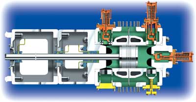
i want to give presentation in my company,topic related with reciprocating gas compressor.
our company product is gas compressor.
please send me good topic on reciprocating compressor technology so i can give presentation 0n it.and also send presentation and any topic on advanced technology on gas compressor.


 Re: presentation on gas compressor technilogy


"Almost" Good Answers: