Previous in Forum: Testing Optical Audio   Next in Forum: Networking Issues
Close
Close
Close
6 comments
Rate Comments: Nested
Guru
India - Member - Sensors Technology Popular Science - Cosmology - Dream, Think and Act United Kingdom - Member - New Member United States - Member - New Member Canada - Member - New Member

Join Date: Aug 2006
Location: AM-51, Deen Dayal Nagar, Gwalior, Madhya Pradesh, MP 474001, India
Posts: 3418
Good Answers: 32

Precision Clock Source 0.01Hz to 10kHz in Steps of 0.01Hz

08/23/2010 12:09 AM

Hello Engineers

I am looking for small PCB that can provide Precision clock source 0.01Hz to 10kHz in steps of 0.01Hz using 6 sets of BCD push wheel switches. Accuracy required is 0.001% of the set frequency or 10ppm. Up to 100ppm can also be considered.

Any one having an idea to make this precision low frequency clock can write to me or discuss here for design possibilities.

If I set 9999.99 in push wheel switches then I should get the same frequency at the output.

Pulse width 1us for sll frequencies is OK.

4"x4" PCB is OK.

__________________
Prof. (Dr.) Shyam, Managing Director for Sensors Technology Private Limited. Gwalior, MP474001, India.
Register to Reply
Interested in this topic? By joining CR4 you can "subscribe" to
this discussion and receive notification when new comments are added.

"Almost" Good Answers:

Check out these comments that don't yet have enough votes to be "official" good answers and, if you agree with them, vote them!
Power-User

Join Date: May 2010
Location: Cambridge, MA
Posts: 390
Good Answers: 82
#1

Re: Precision Clock Source 0.01Hz to 10kHz in Steps of 0.01Hz

08/27/2010 10:31 AM

I see your question has 23 views, but no answers. Speaking of the electronics principle underlying an instrument or circuit board performing this function, a programmable divider is a simple circuit that gives you fout = fin / N, where N is an integer. There are chips that'll accept an input for N, such as from a thumbswitch. It's easy to choose N large enough such that you'll have adjustability in the 0.01Hz region, but because we're talking about 1/N, you won't be able to change fout in exactly 0.01Hz steps. No, instead you want the function fout = fin * N / k, where k is a constant so you can scale the circuit to give you 0.01Hz steps.

If the steps were larger, much larger, you could consider a phase-locked-loop, or PLL, which gives us fout = fin * N by incorporating our simple 1/N divider inside a feedback loop. The operating principle for a PLL is that the frequency step size you get is equal to the phase-detector reference frequency, fref, and the settling time of the circuit is at least a factor of 10x or so longer than the period of this frequency. So, if you had a fref = 0.01Hz reference, you'd have a 0.001Hz or 15-minute settling time. Ouch! No, instead you'd want a higher fref, something reasonable like 1kHz. This is where the concept of the ratio of fmax to the fout step size comes in, and in your case it's fmax / fstep = 10kHz / 0.01Hz = 106, which means fmax would be 1GHz, oops that's pretty high! But we could use fref = 100Hz so that fmax = 100MHz, that's not so bad at all. The settling time could be as fast as 100ms, that's not so bad. We'd divide the PLL output by 10,000 to get your 0.01Hz steps to 10kHz. Simple. But, oops, not so fast! You said you wanted 0.01Hz to 10kHz in steps of 0.01Hz, which means our PLL's voltage-controlled-oscillator, or VCO, would have to work from 100Hz to 100MHz, and I'd can't think of one that can do that.

All this discussion is a long way of getting to the proper electronic solution to your need, which is to use Direct Digital Synthesis, or DDS. This is a much more complicated technique and we have first reviewed the simple possibilities, to rule them out, so we'd know that a more complex approach was necessary. In the DDS concept we can use our 1/N idea, but we feed its output to a phase accumulating counter, and we feed that to a phase-to-output lookup table. This table could present a number for a DAC to give us a sine wave, or it could present the transition point for a square-wave. Since phase goes as time, or 1/f, our 1/N divider is translated to a proportional-to-N result, where fout = N * fref / constant.

About 20 years ago, when I first used the DDS technique, we purchased Sciteq VDS-3A cards, which are much as you describe. These worked to 3MHz, and accepted parallel programming logic inputs. A Google search shows the VDS-3A was immortalized in our research paper. Sciteq was acquired by Osicom (renamed to Sorrento Networks), and they have moved on to better pastures, and the VDS-3A is apparently now obsolete.

As the drawing shows, the DDS approach is complicated, but there are many chips available to perform the task. Analog Devices specializes in these chips, and one simple inexpensive one to consider is their AD9833, in stock for $7.45 at Newark. This chip has fmax / fstep = 1.25 x 10⁸, and if you run it with a 2.5MHz frequency reference, it'll give you 0.01Hz frequency-step resolution, from DC to 0.01Hz to 1.25MHz, or well above the 10kHz maximum you're seeking.

Being a simple 10-pin chip, it's programmed with a 3-pin serial interface, called SPI, and it can't directly accept the six BCD switches you have in mind. For that you need to add a microprocessor with some simple coding.

You can find many sources of small circuit boards containing a microprocessor and a DDS chip, on the web. Most of these are offered by hams, and are intended for upgrading old non-digital transceivers, etc., by adding a digitally-tunable VFO. For example, the $50 board offered by N3ZI, which uses the AD9834. Or the DDS-60 kit from AmQRP, which uses the AD9851, and which is controlled from your PC, so it doesn't even have a processor on the PCB. There are many others, some of which also have open-source software, which you could modify for your thumbswitches.

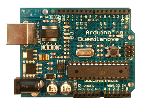
You are interested in a very low frequency, low enough that the DDS phase-accumulator counter, etc., can be implemented in software. Writing the control program for a powerful DDS chip can be a complicated business. It may be easier to bypass the chip and go ahead and implement the whole function in software. Here's one example, and here's another, for the popular Arduino, with a software listing.

Whatever your final solution to the problem is, it's bound to employ DDS technology.

__________________
Thanks, Win
Register to Reply Score 1 for Good Answer
Guru
India - Member - Sensors Technology Popular Science - Cosmology - Dream, Think and Act United Kingdom - Member - New Member United States - Member - New Member Canada - Member - New Member

Join Date: Aug 2006
Location: AM-51, Deen Dayal Nagar, Gwalior, Madhya Pradesh, MP 474001, India
Posts: 3418
Good Answers: 32
#2
In reply to #1

Re: Precision Clock Source 0.01Hz to 10kHz in Steps of 0.01Hz

08/27/2010 2:29 PM

Dear Winfield Hill:

Thanks for nice information. I think these programmable frequency test boards are reasonably priced and I can say they are good work.

I am looking for minimum 0.01% accurate frequency value right from 0.01Hz to 1kHz.

I could generate 1ppm accurate frequencies down to 0.0005Hz or repeat time period as high as 2000.000 +/- 0.002 seconds in my old design ST1006 and ST2006. Those designs are big instrument box of 2U and 1U size and are actually waveform generators having very accurate repeat rate with +/-1ppm accuracy.

I have digitally synthesized frequency source in my ST1006 design but I had serious problem when I could not derive the integer frequency from period like 1/3, 1/11, 1/13 etc. I could not get integer value for period for 3Hz, 6Hz, 7Hz, 9Hz, 11Hz, 13Hz etc. This made my waveform matrix to be limited to numbers that could generate period into integer numbers.

I am now looking for that can generate 0.01 Hz to 1 kHz and still remain very accurate even for 0.001Hz for its period as period is used for timing. Just 0.01 Hz count in meter will not do. I need 100.000+/-0.0005 second accurate period for 0.01Hz. I also need precise pulse width for these clock sources programmable in steps of 1us and up to 999uS with +/-1ns accuracy.

My applications are that of a special accurate experimental need. I can easily pay $500 for these designs.

I have finally designed this clock with precise clock rate and also pulse width. I am using approximation method to get to near the period where division is not yielding integer value for frequency. I am truncating at the desired accuracy for the time period and running very precise 10MHz 1ppm/C low jitter clock to keep the time accuracy even for 0.01Hz.

While many people from old generation can easily solve such things, I feel the new generation is not having much interest or capabilities in handling such tasks. All tools are there but brain is empty or filled with something else.

__________________
Prof. (Dr.) Shyam, Managing Director for Sensors Technology Private Limited. Gwalior, MP474001, India.
Register to Reply
Power-User

Join Date: May 2010
Location: Cambridge, MA
Posts: 390
Good Answers: 82
#3
In reply to #2

Re: Precision Clock Source 0.01Hz to 10kHz in Steps of 0.01Hz

08/27/2010 3:22 PM

Hi, Shyam, I'm glad my comments may have been helpful. Since the DDS techniques use a frequency-reference input, you may make that as accurate and stable as you wish. Cheap crystal oscillator modules will usually give you 0.01%, but for a modest cost you can do much better. You could even use a low-cost GPS-stabilized 10MHz reference. They are at least useful for calibrating a cheap adjustable crystal reference.

$500 is a pretty small budget, but the DDS technique is widely known and easy enough to use, that I'm sure you can find a programmer there in India who can do the custom work within your budget. You can chose to have a microprocessor program read your thumbswitches and setup an Analog Devices DDS chip, or you can chose to implement a real-time software DDS program. The latter would require more programming skill, because the processor has to maintain a steady 100us tick, even while checking for changes in the thumbwheels, etc. (you'd use a micro that includes a divider, whose output could be set to 100us, and made to interrupt the processor). So its programming cost would be higher, but you would not have to invest in a special PCB to hold a tiny DDS chip.

Small, low-cost PCBs, with a uP ready to use, are widely available. They are also smaller than your space budget. One of the Arduino offerings (there are several distributors in India) would be an excellent example to consider, and so much fun to learn to use, you might even decide to do the programming yourself!

I might just add that the board you pick does not have to have enough pins to directly read six thumbswitches (24 wires), because we usually use a matrix scheme requiring only 10 wires. You might also elect to use a kepad.

__________________
Thanks, Win
Register to Reply
Guru
India - Member - Sensors Technology Popular Science - Cosmology - Dream, Think and Act United Kingdom - Member - New Member United States - Member - New Member Canada - Member - New Member

Join Date: Aug 2006
Location: AM-51, Deen Dayal Nagar, Gwalior, Madhya Pradesh, MP 474001, India
Posts: 3418
Good Answers: 32
#4
In reply to #3

Re: Precision Clock Source 0.01Hz to 10kHz in Steps of 0.01Hz

08/27/2010 11:14 PM

yes, I will like to explore DDS boards. I use oven controlled oscillators that easily give 1ppm/C stability. Normal AT cut crystals give 5ppm/C stability. I am not using GPS.

Matrix scanning of switches is OK. I am also planning to multiplex them and read 4-bits at a time. For 6 pushwheel switches, I will need 10 wires.

__________________
Prof. (Dr.) Shyam, Managing Director for Sensors Technology Private Limited. Gwalior, MP474001, India.
Register to Reply
Power-User

Join Date: May 2010
Location: Cambridge, MA
Posts: 390
Good Answers: 82
#5
In reply to #4

Re: Precision Clock Source 0.01Hz to 10kHz in Steps of 0.01Hz

08/28/2010 8:57 AM

I finally took a look at your website. I see you have specialized in precision time and timer-based pulse instruments, with high stability and low jitter. Now you're considering long-period frequency-based pulses, which is a new scene. And I see you retain your interest in precision time intervals, even as you're thinking frequency.

The DDS technique has an aspect that's inherent time-stable in that it's clock driven, and makes a new decision at every clock pulse. Earlier I mentioned the simple DDS chip, the AD9833, and I said with a 2.5MHz frequency reference, it would give you 0.01Hz frequency-step resolution, from DC to 1.25MHz. It's potentially very time-precise, making a new decision every 0.4 microseconds, according to an external precise time source. But there is a weakness, which is in the phase-accumulating counter and the lookup table. Looking at the datasheet, we see the AD9833 uses a 28-bit accumulator, but this is truncated for a 12-bit lookup table, which feeds a 10-bit DAC. They say, "Using the full resolution of the phase accumulator is impractical and unnecessary, because this would require a look-up table of 228 entries. It is necessary only to have sufficient phase resolution such that the errors due to truncation are smaller than the resolution of the 10-bit DAC." Clearly this impacts the exact time of the decision point in saying a sine-wave zero-crossing has occurred. The 28-bit accumulator knows, but for low-frequency outputs the fine microsecond-level detail will be lost inside the chip.

I have used some of Analog Devices' more complex DDS chips, which have 14-bit DACs, and therefore 16x better resolution. These also run at faster clock rates.

Often the user has no interest in a sine-wave output. The chips do let you see the MSB of the DAC input, which will give you a square wave. I say "square" but this is limited by the 10-bit (or 14-bit) resolution as mentioned above. Users often take the sine-wave output, filter it, and use a zero-crossing comparator to get a more accurate square wave. But this isn't useful at very low frequencies, nor for the case of a wide frequency range.

If you make a software implementation of a DDS, or NCO, you can work to avoid resolution-limitations in your program. But you will have one new reality, a much more coarse time interval than with the hardware chips, perhaps 5 to 10us, with careful programming. Using a faster processor will help, or a DSP might be even better. A custom digital DDS implementation in an FPGA could help solve these issues. FPGAs have come down in cost, and are easier to program than in the old days.

Xilinx offers $79, $129 and $169 (pictured) Spartan startup kits so you can develop a FPGA design of your own. These work with the free Xilinx ISE webPACK software and can really get you powered up!

__________________
Thanks, Win
Register to Reply
Guru
India - Member - Sensors Technology Popular Science - Cosmology - Dream, Think and Act United Kingdom - Member - New Member United States - Member - New Member Canada - Member - New Member

Join Date: Aug 2006
Location: AM-51, Deen Dayal Nagar, Gwalior, Madhya Pradesh, MP 474001, India
Posts: 3418
Good Answers: 32
#6
In reply to #5

Re: Precision Clock Source 0.01Hz to 10kHz in Steps of 0.01Hz

08/28/2010 12:51 PM

ST2006 design was very special. As I have said before, my designs work with perfect integers and there is a allowed pull up table that user can use to select the frequencies from 0.0005Hz to 1000Hz. Good thing is that it is in decimal numbers like 1,2,5,10Hz etc. I have avoided 3Hz, 7Hz, 11Hz etc. It is basically a period in which a matrix of 10000 elements at 1kHz rate form a waveform of 8 independently programmable signal types in parallel. Design can be cascaded to few thousands of signals without affecting time accuracy. We never used more than 8 signals and another 8 complementary signals from same machine. If you have 0.0005Hz selected, then in my design it is a 2000s period or 2000,000,0000 bytes/s of information forms an output pattern. This is exactly 20G Byte. Design is cable to generate 10000 times greater data as well but we never needed that much and period will become 20000000s or almost one year period. ST2006 machines actually play that much data synchronized at 100ns intervals with 500ps jitter. Internal clock of 10MHz is very accurate and one can use atomic clock as input at that point to maintain with greater accuracy.

It is very difficult to use such a complicated design for compact portable tasks. That is why I am working now on simpler circuit models. For timing clocks, task is very difficult compared to tune f - measure f - re-tune f and keep doing till you get desired frequency. I need accurate results in a single shot.

Another problem comes from synchronization. How accurately and in least time one can synchronize and generate clock signals. I am looking for 100ps and in worst case 500ps synchronization time.

__________________
Prof. (Dr.) Shyam, Managing Director for Sensors Technology Private Limited. Gwalior, MP474001, India.
Register to Reply
Register to Reply 6 comments

"Almost" Good Answers:

Check out these comments that don't yet have enough votes to be "official" good answers and, if you agree with them, vote them!

Previous in Forum: Testing Optical Audio   Next in Forum: Networking Issues

Advertisement