
Range
of Motion Video (profile)....
http://www.youtube.com/watch?v=P_vF3ooVwAU
Range
of Motion Video (front)....
http://www.youtube.com/watch?feature...&v=E7CEwnOFnCk
I've
been working on this (hobby status) on and off over the last fifteen years or
so.... a mechanism that immediately begins to rotate in either direction with an
imbalancing displacement of as little as one degree. With repeated periodic
displacements of as little as five to seven degrees its rate of rotation rapidly
approaches about a 100 to a 150 rotations per minute over the course of just
eight to ten repetitions, all while overcoming only negligible frictional
resistance from the main axel (equipped with bearings). It may have some
applications for extracting rotational motion more efficiently from wind and
wave and maybe a couple of other things too.... or it may just be a work of
art.
A
uniquely balanced mechanical arrangement, its motion is pendulous.... but unlike
a simple pendulum which has two possible positions of equilibrium (stable when
down and un-stable when up), this Pendulum, because of the way it's balanced,
actually has four possible positions of equilibrium.... two un-stable positions
alligned with the force of gravity (up or down vertically).... and two stable
positions perpendicular to the force of gravity (positioned to either side
horizontally).
Gravity isn't
being switched or turned on and off, the influence that gravity has on the
Mechanism is being changed by changing its condition. I'm
getting the Mechanism to rotate by periodically changing its condition. The
Control Lever at the rear (connected to the Calibrated Spring) is the part
that's periodically moved back and forth (3 to 5 degrees approx.) and is fixed
to the Main Axel (white) and Sun Sprocket (gold with white center) of the
Planetary Chain and Sprocket arrangement. The Planet Sprocket (black, with the
Pendulum that is fixed to it) is affected through the imbalancing action of the
Sun Sprocket, transmitted to it by the Chain.
It swings
to one side, and then, by changing the condition of the Mechanism at the
appropriate time, the Pendulum continues its swinging motion (taking an
eliptical path) to the other side without losing kinetic energy gained. I
believe that's why it begins to rotate so quickly and
forcefully.
It's
a pendulous Mechanism that rotates relatively forcefully at the first
introduction of a relatively slight imbalancing force. The input
force needed to imbalance the Mechanism, delivered to the system via the Control
Lever, is sensibly comparable in every way to standing a pencil on end, holding
it at the top and moving it back and forth an inch or so, which is exactly what
I feel during testing like that shown in the videos.... almost
nothing.
The
actual driving force needed to cause rotation of the Mechanism as a whole can't
be imparted to the Planet Sprocket by the Sun Sprocket via the Chain because the
Sun Sprocket doesn't move in such a way as to impart rotational motion to the
Planet Sprocket which leaves gravity as the only other driving force available
to explain why it immediately begins to rotate in response to a slight
imbalancing force.
In
all the diagrams the length of a line represents the magnitude of a force and
the arrow itself represents the direction of a force, so no mass is explicitly
stated anywhere in the analysis . For
example....
The
situation graphically depicted in the diagram below won't change as long as any
arbitrarily stated magnitude of force for the vector D is uniformly applied as a
standard. In other words.... Whether one arbitrarily states for the vector D a
magnitude of force equal to two ounces or sixteen pounds the resulting
diagramatically shown vector proportions won't change in any way, and the
diagram will remain an accurate representation for both scenarios (two ounces or
sixteen pounds). So, since any arbitrarily stated magnitude of force for the
vector D will result in an identical diagram and identical vector proportions,
for the purpose of analysis, there's no need to state any specific magnitude of
force for the vector D in the diagram.
Any arbitrarily
stated magnitude of force for the vector D (or any other vector in the diagrams)
uniformly applied as a standard gives the magnitude of force associated with any
of the other vectors in the scale drawings of the analysis. For
example....
If
the vector D is made to equal one inch and the arbitrarily stated magnitude of
force associated with it is two ounces (one inch equals two ounces),
then....
A....
3/8 inch equals 0.75 ounces
B....
3/4 inch equals 1.50 ounces
C....
3/4 inch equals 1.50 ounces
D.... 1 inch equals 2.0
ounces
E....
3/8 inch equals 0.75 ounces
F....
F = C + B.... 0 ounces
If,
instead, the vector D is made to equal one inch and the arbitrarily stated
magnitude of force associated with it is sixteen pounds (one inch equals sixteen
pounds), then....
A....
3/8 inch equals 6 pounds
B....
3/4 inch equals 12 pounds
C....
3/4 inch equals 12 pounds
D.... 1 inch equals 16
pounds
E....
3/8 inch equals 6 pounds
F....
F = C + B.... 0 pounds
For
the purpose of analysis the very same numerically un-adorned diagram serves to
describe both of the above scenarios equally well.
The
diagram (below) illustrates both the direction and magnitude of the forces
arising from the various moving parts of the mechanism individually and shows
(FIG. 4) how they ultimately cancel each other out.
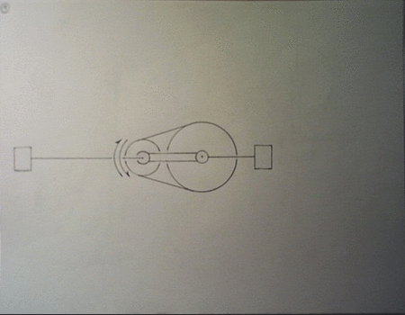
FIG.
1 - Schematic representation of the Chassis.
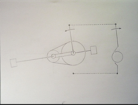
FIG.
2 - The Chassis is fixed in this schematic. The diagram shows the downward force
A of the Pendulum and the resulting force B on the Planet Sprocket.
FIG.
3 - The Sun Sprocket is fixed in this schematic. The Chassis and the Planet
Sprocket are free to rotate. The diagram shows the downward force D of the
planet sprocket. The force C on the Planet Sprocket is the result of the force D
after the force E from the oppositely situated Counter Weight (fixed to the
chassis) is subtracted, or.... D minus E equals C.
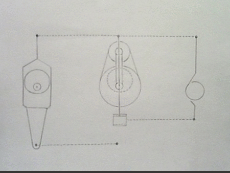
FIG.
4 - The Sun Sprocket is fixed in this schematic. The Planet Sprocket with its
attached Pendulum and the Chassis are free to rotate. The equal and opposite
forces B and C acting on the Planet Sprocket effectively cancel each other out,
or.... B plus C equals F.

A
series of schematic diagrams (below) show how the equal and opposite forces B
and C cancel each other out at various points around 360 degrees (the sun
sprocket is fixed for this part of the analysis), presented here as an
animation....
In
order to render the mechanism purturbable the sun sprocket must be free to move.
When it's free to move the mechanism's equilbrium (which was stable at all
points around 360 degrees when the sun sprocket was fixed) can be purturbed via
the chain by a slight change in the position of the sun sprocket by means of the
control lever, which is fixed to the same axle as the sun sprocket. This is also
the condition in which four distinct positions of equlibrium emerge. I found a
video of an older model (balanced the very same way as the current model) that
clearly demonstrates the four possible positions of equilibrium that arise when
the sun sprocked is freed to rotate (two stable and two un-stable), appearing in
the same order as listed below the video. The video also shows how the mechanism
can be caused to rotate as easily in one directon as the
other....
http://www.youtube.com/watch?v=OoF3zUu8G9s]Images
1.
Pendulum horizontal to the left, stable equilibrium.... the mechanism can't be
caused to rotate by the action of the control lever from this position.
2.
Pendulum horizontal to the right, stable equilibrium.... the mechanism can't be
caused to rotate by the action of the control lever from this position.
3.
Pendulum down vertically, un-stable equilibrium.... the mechanism can be caused
to rotate by the action of the control lever from this position.
4.
Pendulum up vertically, un-stable equilibrium.... the mechanism can be caused to
rotate by the action of the control lever from this position.
This
constitutes a perturbable form of balance that can result in immediate onset of
rotation (in either direction), presented here as an
animation....

A
problem then arises as a direct result of the sun sprocket being freed to rotate
for the purpose of perturbing the mechanism's equilibrium via the chain. The
varying forces arising from changing mass distribution during rotation that were
formerly transmitted directly to the stand when the sun sprocket was fixed now
come to bear on the control lever instead. The diagram (below) shows the
downward force D on the Planet Sprocket. The force H on the Sun Sprocket is the
result of the force D, and the force I on the Control Lever is the result of the
force H. The Mechanism is not balanced or in equilibrium in this diagram because
there is no equal and opposite force to counter the force
I.

That's
where the calibrated spring comes in.... it's mounted on the back of the
Mechanism (depicted to the right in the diagram below). The lower end X is fixed
to the stand the mechanism is mounted on. The upper end Y is connected to the
Control Lever. The diagram (below) shows how the equal and opposite forces I and
J effectively cancel each other out and equilibrious balance Q is the result,
or.... I plus J equals Q. The Mechanism is in a state of compensated
equilibrium, the sum of all forces acting on the control lever is
zero.

I
want to minimize the magnitude of the input force needed to perturb the
system.... the calibrated spring variably compensates for and cancels out the
varying force coming to bear on the control lever due to changing mass
distribution. The sum of the equal and opposite forces I and J coming to bear on
the control lever equals zero at all times during rotation as shown (below).
This constitutes a compensatory form of balance. It reduces the input force
needed to cause immediate onset of rotation to the level of that needed to
overcome only frictional resistance from the Main Axel (equipped with bearings),
presented here as an animation....
Timing....
the stage of the analysis that illustrates the variable timing function of the
adjustable Cam and Standing Lever. The diagram below shows the Cam that's
located directly behind the Sun Sprocket. It's fixed to the Chassis and rotates
with it. The Standing Lever (visible in the videos as a second lever moving back
and forth in front of the Control Lever) and the corresponding position of the
Cam that's moving it are depicted to the left.

The
Planet Sprocket with its attached Pendulum, the Chassis and the Sun Sprocket are
all free to rotate in the following schematic diagrams, presented as an
animation....
By
linking the Standing Lever to the Control Lever the mechanism's position can be
synchronized with the position of the Control Lever at all points around 360
degrees.... analysis is on going.


 Re: An Exploratory Research Mechanism


"Almost" Good Answers: