Previous in Forum: PWHT of SS 316 Clad Vessel   Next in Forum: Gas Handling License
Close
Close
Close
6 comments
Rate Comments: Nested
Participant

Join Date: Mar 2013
Posts: 2

Figuring Out Pump Impeller Size for Pump Design Based on Given Motor?

03/17/2013 2:26 PM

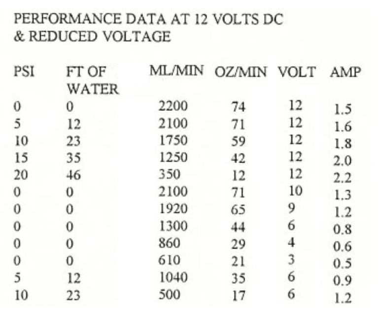
Hi, I have a gear pump motor and I'm throwing away the gear pump and designing and building a centrifugal pump to attach to it. I want to get the highest flowrate possible and I'm using a 3D printer to design and build an impeller and housing for my new pump. I'm using the motor from this pump here:

http://www.greylor.com/productline_pq1224.htm

I've been doing a lot of calculations and I just don't trust my results.

There is no specs about the motor itself on the manufacturers website, but it's an electric motor so I just did a basic hp calculation of (V*I*Eff)/760 = hp

I chose where it was operating at its highest amps and 12volts and assumed an 85% efficiency. so I get an available horsepower of 0.0295 hp.

Now from the curves, I get I chose my head value to be the head value at BEP on the curve, or 85% of max head, which is ~ 14.02m

given that, I calculate the highest flow rate I can get that has a motor power required under the max my motor can get, 0.0295hp.

After some messing around I got a flow rate of 0.31 m^3/h, which requires 0.0287 hp

fluid power= (Q*p*g*h)/3600 = (0.31*998*9.81*14.02)/3600 = 0.0158hp

shaft power= 0.0194/0.65<--assumed pumpeffy

= 0.0244hp

motor power required= 0.0244/0.85= 0.0287hp, which is a safe distance from the motor power available of 0.0295 hp. my main issue here is that I'm keeping the head value of 14.02m constant to find a hp value closest to my motor, which I feel is incorrect.

Now for the impeller diameter I don't feel like I'm using the equations right:

impeller circumference = pi*d

Velocity= circum*RPM <--- I chose the RPM from the pump curve, which states 3500rpm

head = V^2/(2*g)

and work back given my head value of 14.35m

14.02m= 45.997ft

V= sqrt(45.997ft*2*32 ft/s^2) = 54.257 ft/s = 3255.41 ft/min

circum = v/RPM = 3255.41 ft/min/3500RPM = 0.930' = 11.16"

impeller diameter = 11.16"/pi= 3.55" = 9.017 cm.

This diameter seems absurdly large for the given pump. I would have guessed at most half of that.

The equation also doesn't relate to flow rate. I can't seem to find an equation that relates to flow rate for impeller diameter.

Any help would be appreciated.

Thanks.

(PS this is for a hobby design, not professional)

Register to Reply
Interested in this topic? By joining CR4 you can "subscribe" to
this discussion and receive notification when new comments are added.

"Almost" Good Answers:

Check out these comments that don't yet have enough votes to be "official" good answers and, if you agree with them, vote them!
Guru
Technical Fields - Technical Writing - New Member Engineering Fields - Piping Design Engineering - New Member

Join Date: May 2009
Location: Richland, WA, USA
Posts: 21017
Good Answers: 795
#1

Re: Figuring out pump impeller size for pump design based on given motor???

03/17/2013 3:52 PM

Flow rate is more closely related to axial dimensions (and rpm) of the impeller. Diameter (and rpm) relates more closely to pressure.

__________________
In vino veritas; in cervisia carmen; in aqua E. coli.
Register to Reply
Guru

Join Date: Oct 2008
Posts: 42355
Good Answers: 1693
#2

Re: Figuring out pump impeller size for pump design based on given motor???

03/17/2013 5:08 PM

9cm may, or may not be too big, depending on many factors. Sounds optimistic, but who knows.

If you are 3D printing, start there and trim if needed.

Even the pros don't get optimum performance without some tuning.

Send some pictures, please.

Register to Reply
Guru
Hobbies - DIY Welding - New Member

Join Date: Apr 2008
Location: Bristol, Tennessee
Posts: 1177
Good Answers: 58
#3

Re: Figuring Out Pump Impeller Size for Pump Design Based on Given Motor?

03/18/2013 8:17 PM

Why bother to print an impeller which may not withstand abrasion and cavitation? Just find a pump head or impeller with the curve you need. Let others do the R&D. Not easy to print the mounting thread, or machine it either. Blind inside threads ain't no fun.

__________________
mike k
Register to Reply
Guru

Join Date: Sep 2008
Posts: 706
Good Answers: 32
#4

Re: Figuring Out Pump Impeller Size for Pump Design Based on Given Motor?

03/19/2013 1:36 PM

I saw no mention of what you are pumping or the application. If there was a gear pump in place I would assume that the fluid is an oil or some other viscous material since one generally does not use a gear pump for non-lubricating fluids unless there is an external method of timing the gears to prevent tooth to tooth wear. Viscosity will have a major detrimental affect on a centrifugal impeller output when it gets above a certain range. Since a gear pump is a "positive displacement pump" it also means that your capacity vs. discharge pressure are pretty constant and have a linear relationship to speed as opposed to the the TDH and flow of a centrifugal which follow the curve and will vary based on the system losses. Hopefully you will not be operating anything of a critical nature will this "design" like your home furnace heating oil pump.

__________________
Spinco
Register to Reply
Participant

Join Date: Mar 2013
Posts: 2
#5

Re: Figuring Out Pump Impeller Size for Pump Design Based on Given Motor?

03/24/2013 12:00 PM

Sorry for the late reply. Have been incredibly busy.

Pumping water, nothing else.

There will be no major application for this other than simple fun and learning so no worry about safety issues.

Thanks for the replies. I've made a general housing and in the process of printing off a few different sized impellers to test.

Pictures as requested:

Register to Reply
Power-User

Join Date: Feb 2008
Location: Northeast Ohio, USA
Posts: 267
Good Answers: 9
#6

Re: Figuring Out Pump Impeller Size for Pump Design Based on Given Motor?

03/26/2013 4:09 PM

Wow! You've given us a tough one here. The basic premise of your investigations is correct as far as it goes. Again, as I have said in other discussions, centrifugal pumps are bound by the Laws of Affinity. In respect to the speed of the pump, here are some facts. There is only one way to increase or decrease the head (pressure) that a centrifugal pump will produce. That is to vary the "tip speed" of the impeller. If, for instance you have an impeller with a 5" diameter (I am from the US so you'll have to bear with me on this), and it is spinning at 1750 RPM, the tip speed would be 20.825 fps (English measurement again - sorry). There are two ways to increase the tip speed you can 1) - Speed up the driver (say from 1750 RPM to 2000 RPM) 2) - increase the diameter of the impeller thus increasing the travel of the tip of the impeller in each revolution. Now the Laws of Affinity say that the Head changes in proportion to the square of the speed. That is how you can predict the head you can get from the impeller. These laws also say that the flow changes in direct proportion to the tip speed. As you can see, these predictions are based on the CHANGES in the tip speed. The flow, for instance, is relative to the height and type of the impeller. A wider, thicker if you will, impeller delivers more flow than a lower, more narrow impeller. So you see where i am going with this. The element that is missing is satisfied by - testing. You test the impeller and adjsut as necessary with predictable calculations. You have selected a very tough task. Good luck.

__________________
All that is necessary for the triumph of evil is for good men to do nothing. - Edmund Burke
Register to Reply Score 1 for Good Answer
Register to Reply 6 comments

"Almost" Good Answers:

Check out these comments that don't yet have enough votes to be "official" good answers and, if you agree with them, vote them!
Copy to Clipboard

Users who posted comments:

JB88 (1); lyn (1); mike k (1); Spinco (1); The Commoner (1); Tornado (1)

Previous in Forum: PWHT of SS 316 Clad Vessel   Next in Forum: Gas Handling License

Advertisement