Previous in Forum: Juno   Next in Forum: Does CO2 Level Really Hurt the Bees?
Close
Close
Close
26 comments
Rate Comments: Nested
Power-User
Hobbies - CNC - New Member

Join Date: Feb 2010
Location: Vallejo, CA
Posts: 127
Good Answers: 8

Lens Optics Problem

07/05/2016 9:28 AM

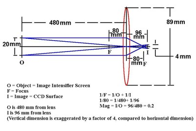
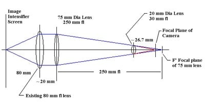
In an effort to get X-ray pictures of the neck with minimum exposure, I have coupled an astronomical camera to a used Image Intensifier. The image output window provides a usable image about 25 mm high. An 80 mm fl lens is spaced so that the output light is collimated, focused at infinity. A 200 mm light path, including a tilt tip mirror, leads to the camera, which is fitted with a 25 mm fl lens, also focused at infinity. This provides the required magnification, about 0.3. The 80 mm lens is an f 0.9, and the 25 mm lens is an f 1.4.

Two issues trouble me. The large lens emits a beam of light over 2 inches in diameter, all parallel rays. The 25 mm camera lens can only intercept a small pencil of this beam, so the majority of the light produced is not focused on the CCD sensor, thus the sensitivity of the overall system is compromised. Of greater concern is the effect of this mismatch of apertures on the resolution of this lens system.

Spacing the large lens out from the II window so that it produces a converging beam, and bringing the 25 mm lens closer to the CCD so that it brings focus to the converging beam would seem a sensible approach to utilizing the light more efficiently. Because of undergraduate laziness, I missed Optics in school, so do not know how to assess the effect of this change on either the magnification or resolution.

I have been assuming that the Image Intensifier tube was the resolution limiting element in the overall system, but it seems plausible that the lens system is a more important, and improvable, limit. Any improvement in the overall resolution of the system would be welcome.

Register to Reply
User-tagged by 1 user
Interested in this topic? By joining CR4 you can "subscribe" to
this discussion and receive notification when new comments are added.

"Almost" Good Answers:

Check out these comments that don't yet have enough votes to be "official" good answers and, if you agree with them, vote them!
Guru

Join Date: Apr 2010
Location: About 4000 miles from the center of the earth (+/-100 mi)
Posts: 9912
Good Answers: 1141
#1

Re: Lens optics problem

07/05/2016 10:58 AM

I think that adjusting the lens locations so that the rays converge from the first lens should work. The 80 mm fl lens would have to be moved farther than 80 mm from the light source. The optical lens formula is 1/f = 1/S1 + 1/S2. f in this case is 80, S1 is the point where the cone of light would converge without the second lens, and S2 would be the new distance from the source.

The position of the second lens can be computed the same way except that since the rays are converging, the "object" is on the same side of the lens as the image, so either S1 or S2 will be negative, but the same formula can be used.

https://en.wikipedia.org/wiki/Lens_(optics)

I'm thinking like you that the resolution would be limited by the image intensifier.

I would look for some optical ray tracing software. There's free and free trial software out there if you don't want to put out any bucks.

Register to Reply
Guru
United Kingdom - Member - New Member

Join Date: Aug 2010
Location: Resting under the Major Oak
Posts: 4347
Good Answers: 181
#2
In reply to #1

Re: Lens optics problem

07/05/2016 1:10 PM

What you’re showing is the Scheimpflug principal.

I used it for architectural photography. The focal length remains the same but the point of focus changes.

__________________
The reports of my death are greatly exaggerated.
Register to Reply
Guru
Engineering Fields - Optical Engineering - Member Engineering Fields - Engineering Physics - Member Engineering Fields - Systems Engineering - Member

Join Date: Apr 2010
Location: Trantor
Posts: 5363
Good Answers: 647
#3

Re: Lens Optics Problem

07/06/2016 9:00 AM

If you supplied more details, you might get more help.

1. What is the size of the camera detector? (Length x width, in mm.)

2. What is the size of the image area of the image intensifier? (Length x width in mm.)

Given the answers to 1 and 2, a single lens could be fitted between them to capture the intensifier's image on the camera.

BUT some other question needs to be asked:

Is your intensifier sensitive to X-ray radiation? Most intensifiers I'm familiar with are sensitive to near infrared.

How many lines of resolution do you need? Does the image intensifier provide this resolution?

Is your astronomical camera a monochrome camera? (It might as well be, since color will do you no good.) How many pixels per mm are there across the detector surface?

How will you compensate for image artifacts, such as the moire' pattern often seen when viewing an image on one digital surface with another digital imaging device? (I.e., one usually sees moire' when viewing a laptop screen with a digital camera.)

__________________
Whiskey, women -- and astrophysics. Because sometimes a problem can't be solved with just whiskey and women.
Register to Reply
Power-User
Hobbies - CNC - New Member

Join Date: Feb 2010
Location: Vallejo, CA
Posts: 127
Good Answers: 8
#4
In reply to #3

Re: Lens Optics Problem

07/06/2016 2:03 PM

The detector is a 6.4 x 4.7 mm CS mount camera in a 1 1/4 inch telescope eyepiece housing, a Starlight Express Superstar.

The vertical dimension of the part of the II field I am using is 20 mm.

This is a Toshiba 16 inch X-ray image intensifier, removed from medical application, probably Cath lab. Similar physics to NIR intensifiers, but with an input phosphor which is X-ray sensitive.

The intensifier, when new, was rated at 20 lp/cm. This is at the input face; at the window this would be 32 lp/mm

The camera is monochrome, just over 1000 x 1300 pixels. I am binning 2x2 for sensitivity, pixel size not being nearly the limit to resolution at this point.

No Moire' effects as the intensifier is really an analog device, using electron optics to focus the electrons from the front face phosphor onto the 30 mm round window. Because the gain of these vacuum tubes falls off toward the edges, I am using the central 20 mm of the window and orienting the long axis of the image vertical.

The system as described, with infinite - infinite focus lens system as described forms a usable clinical tool. I am certain that I am throwing away the majority of the light coming out of the 80 mm lens, and am coming to suspect that a great deal of resolution in the lens system is lost as well, again due to reduction in effective aperture. This may or may not be resolution limiting, but there is Certainly room for improvement in the efficiency of getting the light onto the sensor.

The purpose of the system is to get the views of the neck required by the upper cervical analysis I apply to difficult necks. I went to this to reduce the radiation exposure to my chiropractic patients to an absolute minimum. Any improvement in sharpness or efficiency of light use is welcome in this application.

The lenses and distances are largely fixed, but if this is important in resolution, I want to improve it. The improvement in efficiency of light use will be a bonus.

bob Woolery, DC

Register to Reply
Guru
Safety - Hazmat - New Member United States - US - Statue of Liberty - New Member Engineering Fields - Chemical Engineering - Old Hand

Join Date: Mar 2011
Location: Lubbock, Texas
Posts: 14331
Good Answers: 162
#5
In reply to #4

Re: Lens Optics Problem

07/06/2016 4:59 PM

Define difficult neck: The stiff neck of a really testy old fart!

Use a 16d nail to hold the old fart down on the X-ray table, and irradiate his as* neck really good! That way you can underdevelop the films, and have a sharper X-ray result. Picture a success, patient, well, not so much.

__________________
If it ain't broke, don't fix it. Just build a better one.
Register to Reply
Guru
Safety - Hazmat - New Member United States - US - Statue of Liberty - New Member Engineering Fields - Chemical Engineering - Old Hand

Join Date: Mar 2011
Location: Lubbock, Texas
Posts: 14331
Good Answers: 162
#6

Re: Lens Optics Problem

07/06/2016 5:00 PM

Seriously, I think the ability to either collimate or to focus the X-ray beam maybe your limiting factor.

__________________
If it ain't broke, don't fix it. Just build a better one.
Register to Reply
Power-User
Hobbies - CNC - New Member

Join Date: Feb 2010
Location: Vallejo, CA
Posts: 127
Good Answers: 8
#7
In reply to #6

Re: Lens Optics Problem

07/06/2016 11:44 PM

The x-ray source is 0.3 mm focal spot, and I have gotten considerbly better resolution using film with the same source tube. I want to improve the lens system resolution if possible

Register to Reply
The Engineer
Engineering Fields - Engineering Physics - Physics... United States - Member - NY Popular Science - Genetics - Organic Chemistry... Popular Science - Cosmology - New Member Ingeniería en Español - Nuevo Miembro - New Member

Join Date: Feb 2005
Location: Albany, New York
Posts: 5060
Good Answers: 129
#8

Re: Lens Optics Problem

07/07/2016 8:59 AM

If you could provide even a rudimentary diagram of your set up I think someone here can help, but trying to hold all of this in my head isn't working. I would think you could just throw a longer focal length lens before your 80 mm fl lens in your set up, but I'm sure you would have thought of that which means I'm missing something.

Register to Reply
Guru

Join Date: Oct 2009
Posts: 1460
Good Answers: 30
#9

Re: Lens Optics Problem

07/09/2016 9:22 AM

First off, the resolution of the system is entirely dependent on the sensor (the image intensifier). The optics of the illuminating system play no part in determining the resolution.

Secondly, a conventional X-ray system is a shadow imaging system, so there is no real need for a second lens between object (neck) and image (image intensifier). All you need to do is space the collimating lens to produce a conical rather than parallel beam, and then place the object and sensor in the appropriate positions to achieve the required magnification.

Third, the object you are imaging must be smaller than the collimated beam. Your collimating lens has a focal length of 80mm and and an f number of 0.9, so its diameter is (near enough) 89mm. This means that the object must have a height less than this. Because you want all the light to arrive at a sensor which is much smaller, the illumination should form a conical rather than cylindrical beam. This is true even if you do include a second lens in the image path. Your second lens has a focal length of 25mm and an f number of 1.4, so its diameter is only 18mm.

In practical terms, then, you could aim to image an object up to 60mm high. This is in line with the parameters of 0.3 magnification with a sensor height of 20mm. The illuminating source is placed at a distance from the collimating lens which is greater than its focal length. This produces a conical beam. If the distance from the apex of the cone to the sensor is d, then the distance to the object is 3d and the distance to the focal plane of the lens is 89/22d or 4d.

Fortunately you can vary d by varying the distance of the illumination from the focal plane. Bearing in mind that you are imaging a neck, the focal plane of the lens needs to be more than half a neck away from the centre of the neck, so d = 200mm is a good start. If then the cone apex is at 800mm, the lens equation gives a distance between illumination and focal plane of 88mm.

Register to Reply Score 1 for Good Answer
Power-User
Hobbies - CNC - New Member

Join Date: Feb 2010
Location: Vallejo, CA
Posts: 127
Good Answers: 8
#10
In reply to #9

Re: Lens Optics Problem

07/10/2016 2:26 AM

I've clearly managed to mislead. If I knew how to draw into an e-mail, I would post diagrams. As it is, I'll try to make the issue more explicit. First, the shadowgram part of this imaging system is entirely in the X-ray aspect. As there are no practical collimators or lenses for X-rays, this is strictly the cone of X-ray that emanates from a 0.3mm focal spot, shines through the patient, and hits the 16 inch diameter input screen of the intensifier tube. The phosphor in that input screen emits electrons corresponding to the intensity of X-ray, and these electrons are accelerated through 30 kV and focused onto a 1 inch diameter output screen which absorbs electrons and emits visible (green) light. It is the image at this screen that must be focused onto the 6.4 x 4.7 mm CCD chip.

To address your comments, The sensor in this system is the CCD; the illumination is X-ray, and the optical part of the system starts at the output window of the II. However sharp the image is at the output window, the resolution of the lens system must be at least as good if it is not to degrade performance.

The current setup, largely inherited from the original application, puts the 80mm lens collimating the image, and the 25 mm lens on the camera set to infinity brings the image into focus. One consequence of this geometry is that only a small pencil (14 mm by your figures) of the 80 mm beam is utilized. This is an obvious waste of light, especially since any loss of light increases the required patient X-ray exposure. Minimizing exposure was the entire purpose of this project. Overall sensitivity is acceptable, but any improvement in resolution would be welcome.

My reading of materials on telescope optics suggest that effective aperture also influences the resolution of the lens system, and it is this aspect of the overall system unsharpness that I hope to improve. I can see that spacing the 80 mm objective out from the window will produce a converging beam, which can be brought to focus with a camera lens set closer than its focal length. I am constrained by the existing mechanical setup to put the camera lens at about 175 - 200 mm. I have fine adjustment of this distance, but I am coming to believe that just respacing the lenses to capture most of the light would also alter the magnification. A camera lens of appropriate focal length to restore the magnification to something near 0.3 is needed, but I have no notion of how to estimate the required focal length.

I'm confident that this can be calculated by an apt undergraduate Engineering Physics student, but I don't know any. A summarized version of my problem follows:

20 mm object >>80+ mm>>80 mm lens >>200mm>>? lens>>6.4mmCCD image

So the question now is how do I calculate the required focal length of the camera lens and the lens spacings in this relay lens system.

Thanks to all who have tried to help.

bob Woolery, DC

Vallejo, CA

Register to Reply
Guru

Join Date: Oct 2009
Posts: 1460
Good Answers: 30
#11
In reply to #10

Re: Lens Optics Problem

07/10/2016 9:40 AM

Thank you for illuminating the problem. However, I stand by the statement that the optics are not the limiting factor in your image resolution. Indeed, that would be an argument for limiting yourself to one lens in the optical path rather than two.

I would actually be in favour of butchering the camera and using the large lens (for its light-gathering power) focussing directly on the sensor. Using both lenses is equivalent to the design of a Keplerian refractor telescope, which not only is too long for your available space but also provides far too much magnification. Here is a calculator.

Why is the image through the 25mm lens alone not sufficient?

Register to Reply Score 1 for Good Answer
Guru
Engineering Fields - Optical Engineering - Member Engineering Fields - Engineering Physics - Member Engineering Fields - Systems Engineering - Member

Join Date: Apr 2010
Location: Trantor
Posts: 5363
Good Answers: 647
#12

Re: Lens Optics Problem

07/10/2016 5:00 PM

Sorry I didn't follow up sooner with a 2nd reply. I've had internet connection problems.

I've diagrammed a solution for you that uses only the 80 mm fl lens you have. It takes the 20mm high image from the Image Intensifier Screen and re-images it onto the CCD camera surface with a new image height of 4 mm. This gives you a 'magnification' of 0.2. A magnification of 0.2 requires that the object distance be 5X the image distance. So O = 5I. When this information is plugged into the simple lens formula, 1/ F= 1/O + 1/ I, where F = 80 mm, the solution obtained is I = 96 mm and O = 480 mm.

Please be aware that lenses have abberations affecting sharpness such as image flatness, pincushion or barrel distortion, and coma. So the lens you have will produce an image as I've shown, but whether that image is a high quality image depends on the quality of the lens for this particular purpose. (You might even get some color fringing if the phosphor in the Image Inensifier Screen has a broad band spectrum.)

Here's the sketch:

__________________
Whiskey, women -- and astrophysics. Because sometimes a problem can't be solved with just whiskey and women.
Register to Reply
Guru
Engineering Fields - Optical Engineering - Member Engineering Fields - Engineering Physics - Member Engineering Fields - Systems Engineering - Member

Join Date: Apr 2010
Location: Trantor
Posts: 5363
Good Answers: 647
#13
In reply to #12

Re: Lens Optics Problem

07/11/2016 10:25 AM

Here's another solution:

Using a 40 mm diameter lens (since your initial image is only 20 mm high, there is no need for an 80 mm diameter lens) with a focal length of 60 mm, the 5:1 image size reduction (0.2 'magnification') puts the Image Intensifier Screen at 360 mm from the center of the lens and the CCD surface 72 mm from the center of the lens.

I.e., 1/f = 1/O + 1/I ==> 1/f = 1/5I + 1/I == 6/5I; putting f = 60 mm and solving for I we get I=72 mm, which means O=360 mm. [1/60 = 1/360 + 1/72].

Here's a lens from Edmund Optics that meets these specs and might work for you:

http://www.edmundoptics.com/optics/optical-lenses/achromatic-lenses/vis-nir-coated-achromatic-lenses/49379/

With this lens the 'back focus' is 50.29 mm, so the 'effective center' of the lens is 60 - 50.29 = 9.71 mm from the axial contact point of the rear surface. So your CCD surface should be 72 - 9.71 = 62.29 mm from the rear surface of the lens.

(I suggested this 2nd solution because this shorter focal length lens yields a more compact system. Be aware though that, in general, the shorter the focal length is, the higher the lens aberrations will be. Camera lenses are expensive due to the need to correct for all the aberrations and yield a sharp image over a large flat imaging surface.)

__________________
Whiskey, women -- and astrophysics. Because sometimes a problem can't be solved with just whiskey and women.
Register to Reply
Power-User
Hobbies - CNC - New Member

Join Date: Feb 2010
Location: Vallejo, CA
Posts: 127
Good Answers: 8
#14
In reply to #13

Re: Lens Optics Problem

07/11/2016 1:44 PM

Single lens solutions suffer from efficiency of light use issues worse than the infinite-infinite system I have now. Two lines of reasoning lead to this conclusion. First, comparing the angle subtended by the 80 mm lens diameter lens at its focal distance with the angle subtended by the same lens at 480 mm. I get a total solid angle at 80mm as 45 degrees. Out at 480 mm, the angle subtended by the lens is 9.5 degrees. From an inverse square standpoint, the illumination should decrease by 80^2 / 480^2 or .028. The aperture mismatch for the infinite- infinite system should be the ratio of the areas of the two lenses or 49 pi /1600 pi = .030. It appears that either setup only uses about 3% of the potential light. I hope to do better.

To address another aspect of the problem that I think is being misunderstood. However sharp the image is when displayed on the 1 inch output window, out of focus conditions can only degrade the system resolution. Besides focus, other resolution limiting phenomena also degrade the final image. I understand that the aperture and resolution are related, and bigger is better.

Physical constraints like the size of the X-ray room force me to utilize the folded path and giant objective inherited from the previous application. I do have room to space it out from the window as much as 10 mm, 25 with some struggle. The CS lens mount allows spacing the C-mount lens as much as 5 mm closer than infinite focus, so able to focus a converging beam. I believe that this will influence the magnification of the optics, which need to be close to 0.3. Spacing the 80 mm lens out by 25 mm brings the point on the cone where the converging beam has a diameter of 14 mm gives a distance of 117 mm. inserting a converging lens at this point intercepts most of the light, and brings the image to focus on the CCD. The remaining question is the focal length of that second lens to make magnification near 0.3,

Register to Reply
Guru
Engineering Fields - Optical Engineering - Member Engineering Fields - Engineering Physics - Member Engineering Fields - Systems Engineering - Member

Join Date: Apr 2010
Location: Trantor
Posts: 5363
Good Answers: 647
#15
In reply to #14

Re: Lens Optics Problem

07/12/2016 9:43 AM

The problem with light throughput (entendue) you mention here did not seem to be an obvious problem in your initial post.
If light intensity (and thus, capture) is such an issue, why on earth are you using a color camera to acquire a monochrome image? You're throwing away more than 2/3rds of the photons in the RGB filters in the color camera.
Buy a cooled monochrome camera and use it instead. You can get a very good cooled, low noise, monochrome camera from Orion Telescopes and get a much better signal to noise ratio than you'd get with the color camera you're using now. This one for example:
http://www.telescope.com/Astrophotography/Astrophotography-Cameras/Orion-StarShoot-G3-Deep-Space-Monochrome-Imaging-Camera/pc/-1/c/4/sc/58/p/101473.uts

(Sorry, the hyperlink process is not working for me. You'll have to copy and paste the link.)

__________________
Whiskey, women -- and astrophysics. Because sometimes a problem can't be solved with just whiskey and women.
Register to Reply Off Topic (Score 4)
Guru
Engineering Fields - Optical Engineering - Member Engineering Fields - Engineering Physics - Member Engineering Fields - Systems Engineering - Member

Join Date: Apr 2010
Location: Trantor
Posts: 5363
Good Answers: 647
#16
In reply to #15

Re: Lens Optics Problem

07/12/2016 12:36 PM

Correction - I checked and noticed that the camera you are using is in fact monochrome. My comment above can mostly be ignored - except that the cooled monochrome camera I suggested will give you a better signal to noise ratio.

__________________
Whiskey, women -- and astrophysics. Because sometimes a problem can't be solved with just whiskey and women.
Register to Reply
Guru
Engineering Fields - Optical Engineering - Member Engineering Fields - Engineering Physics - Member Engineering Fields - Systems Engineering - Member

Join Date: Apr 2010
Location: Trantor
Posts: 5363
Good Answers: 647
#17
In reply to #16

Re: Lens Optics Problem

07/12/2016 1:47 PM

If you add a large (75mm dia), long focal length (~250 mm) lens behind your existing 80 mm fl lens, then use a 30 mm lens to create the final image, your net throughput should be significantly better. And this should give you the image 'magnification' you want.

__________________
Whiskey, women -- and astrophysics. Because sometimes a problem can't be solved with just whiskey and women.
Register to Reply
Guru
Engineering Fields - Optical Engineering - Member Engineering Fields - Engineering Physics - Member Engineering Fields - Systems Engineering - Member

Join Date: Apr 2010
Location: Trantor
Posts: 5363
Good Answers: 647
#18
In reply to #17

Re: Lens Optics Problem

07/12/2016 2:02 PM

Your 25 mm fl lens (which apparently has a diameter of about 18 mm) should work about as well as the 20 mm dia lens I show. Your net magnification would be about 0.28, which is close to what you want.

There are other ways to approach this. This is a simple example. The key, as I see it, is to place a 2nd lens behind your 80 mm lens, as I show in my sketch.

__________________
Whiskey, women -- and astrophysics. Because sometimes a problem can't be solved with just whiskey and women.
Register to Reply
Guru

Join Date: Oct 2009
Posts: 1460
Good Answers: 30
#19
In reply to #17

Re: Lens Optics Problem

07/12/2016 6:10 PM

I have redrawn this diagram to illustrate the futility of this whole exercise. Some of the light from the off-axis object misses the final lens, and some of it even misses the middle. The final lens, placed as it is at a distance close to its focal length from the sensor, achieves very little in the way of shortening the optical path and diminishes the light-gathering power. If it can be removed from the optical path and replaced by a large intermediate lens, as suggested by Usbport but with a shorter focal length alone, so much the better.

Register to Reply Score 1 for Good Answer
Guru
Engineering Fields - Optical Engineering - Member Engineering Fields - Engineering Physics - Member Engineering Fields - Systems Engineering - Member

Join Date: Apr 2010
Location: Trantor
Posts: 5363
Good Answers: 647
#20
In reply to #19

Re: Lens Optics Problem

07/12/2016 7:30 PM

I don't have access to a lens design program now. Wish I still did. GA

__________________
Whiskey, women -- and astrophysics. Because sometimes a problem can't be solved with just whiskey and women.
Register to Reply
Power-User
Hobbies - CNC - New Member

Join Date: Feb 2010
Location: Vallejo, CA
Posts: 127
Good Answers: 8
#21

Re: Lens Optics Problem

07/18/2016 10:40 PM

For those who have been following, a few answers have emerged. Adjkustment range allowed spacing the 80 mm lens out nearly 8 mm from its previous position. Once focus was achieved, magnification went from .3 to about .25, so the field of view of the system is reduced. A good deal better focus was achieved, perhaps reflecting improved resolution by making somewhat better use of available aperture.

Thanks for the help, folks. The conversation clarified my limited understanding.

Register to Reply
Guru
Safety - Hazmat - New Member United States - US - Statue of Liberty - New Member Engineering Fields - Chemical Engineering - Old Hand

Join Date: Mar 2011
Location: Lubbock, Texas
Posts: 14331
Good Answers: 162
#22
In reply to #21

Re: Lens Optics Problem

07/19/2016 12:33 PM

Glad this worked out for you. I have followed, and learned something about the topic as well.

__________________
If it ain't broke, don't fix it. Just build a better one.
Register to Reply
Guru

Join Date: Oct 2009
Posts: 1460
Good Answers: 30
#23
In reply to #21

Re: Lens Optics Problem

07/19/2016 4:46 PM

Yes, I'm glad you have sorted it. For the record, it is always easier to focus with a wide-open (large aperture) lens, because the depth of field is smaller. However sharpness of focus is not the same as resolution. No lens is at its best resolving power at full aperture and stopping a lens down both improves the image sharpness and also minimises the chromatic aberration. However in the present context a reduction in exposure time may be preferable to aiming for the highest resolution.

I'm also puzzled by your magnification and field of view statement. For a given size of sensor in an optical system, there is an inverse relationship between the magnification and the field of view

Register to Reply
Guru
Safety - Hazmat - New Member United States - US - Statue of Liberty - New Member Engineering Fields - Chemical Engineering - Old Hand

Join Date: Mar 2011
Location: Lubbock, Texas
Posts: 14331
Good Answers: 162
#24
In reply to #23

Re: Lens Optics Problem

07/20/2016 11:46 AM

That sounds contradictory to me. When I was an avid photographer (back when film and paper were used), I found that a narrow opening of the same lens produce the deepest depth of field. In other words, in a shot where the background objects/people were important to the composition, a larger f/ number was used, and if only the prime object was needing tight focus, a smaller f/ number was used.

In small f/ number shots, it is absolutely critical the camera not change distance between focusing and taking the shot.

Pretty much in agreement with the rest of your comments, just not with depth of field argument.

__________________
If it ain't broke, don't fix it. Just build a better one.
Register to Reply
Guru

Join Date: Oct 2009
Posts: 1460
Good Answers: 30
#25
In reply to #24

Re: Lens Optics Problem

07/20/2016 5:31 PM

We are not in disagreement. You say that if only the prime object needs tight focus a smaller f/ no is used. That is also what I say, from my experience in focussing with a manual focus SLR (and also focussing a darkroom enlarger). This is exactly the OP's situation, as he is trying to focus a flat image and does not need a great depth of field.

Register to Reply Score 1 for Good Answer
Guru
Safety - Hazmat - New Member United States - US - Statue of Liberty - New Member Engineering Fields - Chemical Engineering - Old Hand

Join Date: Mar 2011
Location: Lubbock, Texas
Posts: 14331
Good Answers: 162
#26
In reply to #25

Re: Lens Optics Problem

07/21/2016 1:58 PM

Copy that! Thumbs up!

__________________
If it ain't broke, don't fix it. Just build a better one.
Register to Reply
Register to Reply 26 comments

"Almost" Good Answers:

Check out these comments that don't yet have enough votes to be "official" good answers and, if you agree with them, vote them!
Copy to Clipboard

Users who posted comments:

Bayes (1); drbobwoolery (5); James Stewart (5); phph001 (5); Rixter (1); TonyS (1); Usbport (8)

Previous in Forum: Juno   Next in Forum: Does CO2 Level Really Hurt the Bees?

Advertisement