Previous in Forum: Advise on Preparation Of Load Schedule   Next in Forum: Intertripping in Power System
Close
Close
Close
31 comments
Rating: Comments: Nested
Anonymous Poster #1

Relays and Contactors in Control Circuit

11/22/2016 3:58 AM

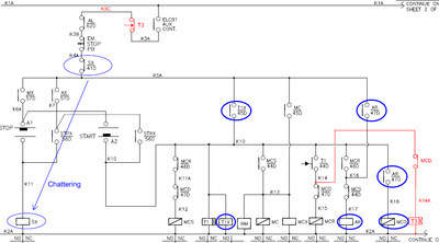
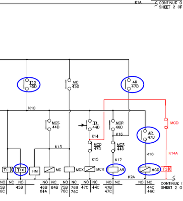
Have any one had an experience of using different make contactors, timers & relays in a control circuit. What are the possible pitfalls of using different contactors , relays in a circuit?
1) For example closing & releasing times of contactors of diferent makes are obviously different.Does this affect the operation of circuit in certain situations? If so what are that situations?
2) I noticed a siemens make power contactor had closing time specification of 17-30ms. So for 50Hz, 1 cycle=20ms. Then How come they specified closing time starting from 17ms?

Reply
Interested in this topic? By joining CR4 you can "subscribe" to
this discussion and receive notification when new comments are added.

Good Answers:

These comments received enough positive votes to make them "good answers".

"Almost" Good Answers:

Check out these comments that don't yet have enough votes to be "official" good answers and, if you agree with them, vote them!
Guru
United Kingdom - Member - Indeterminate Engineering Fields - Control Engineering - New Member

Join Date: Jan 2007
Location: In the bothy, 7 chains down the line from Dodman's Lane level crossing, in the nation formerly known as Great Britain. Kettle's on.
Posts: 32175
Good Answers: 839
#1

Re: Relays and Contactors in Control Circuit

11/22/2016 4:14 AM

A1) Nothing in a process plant happens in less than a second.

A2) <...they...> Ask "them". "Their" telephone numbers are widely published; <...they...> are, surely, the best people to ask!

__________________
"Did you get my e-mail?" - "The biggest problem in communication is the illusion that it has taken place" - George Bernard Shaw, 1856
Reply
Guru

Join Date: Feb 2011
Posts: 7025
Good Answers: 207
#2
In reply to #1

Re: Relays and Contactors in Control Circuit

11/22/2016 7:43 AM

any and ALL answers can be had @ 1-800 SLACK

Reply
Guru
United Kingdom - Member - Indeterminate Engineering Fields - Control Engineering - New Member

Join Date: Jan 2007
Location: In the bothy, 7 chains down the line from Dodman's Lane level crossing, in the nation formerly known as Great Britain. Kettle's on.
Posts: 32175
Good Answers: 839
#5
In reply to #2

Re: Relays and Contactors in Control Circuit

11/22/2016 9:05 AM

It beats 01999 1PLUTO.

__________________
"Did you get my e-mail?" - "The biggest problem in communication is the illusion that it has taken place" - George Bernard Shaw, 1856
Reply
Guru
United Kingdom - Member - Not a New Member Hobbies - Musician - New Member Hobbies - Fishing - New Member

Join Date: May 2006
Location: Reading, Berkshire, UK. Going under cover.
Posts: 9684
Good Answers: 468
#3

Re: Relays and Contactors in Control Circuit

11/22/2016 8:03 AM

Why should the specified closing time have anything to do with the supply frequency?

__________________
"Love justice, you who rule the world" - Dante Alighieri
Reply
2
Guru

Join Date: Aug 2007
Location: Earth - I think.
Posts: 2143
Good Answers: 165
#4
In reply to #3

Re: Relays and Contactors in Control Circuit

11/22/2016 8:51 AM

1/60 = 0.0166666... seconds (~17ms). The magnetic field takes a finite amount of time to build up, plus the time for the contactor to physically move.

Since the OEM is in an international market they used the maximum frequency (minimum time) of 60hz.

__________________
TANSTAAFL (If you don't know what that means, Google it - yourself)
Reply Good Answer (Score 2)
Anonymous Poster #1
#6
In reply to #4

Re: Relays and Contactors in Control Circuit

11/22/2016 12:56 PM

Hi Kilowatt0,

Imagine Auxiliary contact of make "A" relay is in series with contactor make "B" to energize it, with make "A" has higher release time than contactor "B". Now in case of relay "A" chattering will contactor "B" opens or not.
If the closing and releasing times aren't much useful, why is it specified?

Reply
Guru

Join Date: Dec 2010
Posts: 1686
Good Answers: 116
#12
In reply to #6

Re: Relays and Contactors in Control Circuit

11/23/2016 1:23 PM

Contactor B will only open if the contact of A is open for longer than release time of B. This may have no connection with release time of A.

If you want to energise a circuit from two sources, operate/relese times may decide whether you have "make before break" or "Break before make" action.

Reply
4
Guru
United States - Member - New Member Engineering Fields - Power Engineering - New Member

Join Date: Sep 2006
Location: California, USA, where the Godless live next door to God.
Posts: 4665
Good Answers: 804
#7

Re: Relays and Contactors in Control Circuit

11/22/2016 2:26 PM

1) Yes, it can make a difference under a wide variety of circumstances, but at the same time it makes almost no difference in an even wider variety of circumstances. So without knowing the specifics, the answer remains "maybe..."

2) The closing time for an AC operated device is always shown as a range of time values, because it depends upon the phase angle of the line voltage at the exact it is applied. So how can it be 17ms? Because the closing time is the combination of the flux creation + mechanical actuating time, so if the voltage sine wave was at the peak at that instant the control voltage was applied, the flux strength is almost immediately at full value and the armature begins moving. If the sine wave was at the zero-cross at the moment of the command signal, the maximum flux creation time would be longer by 1/2 of a sine wave, resulting a total actuating time of 30ms.

__________________
** All I every really wanted to be, was... A LUMBERJACK!.**
Reply Good Answer (Score 4)
Anonymous Poster #1
#10
In reply to #7

Re: Relays and Contactors in Control Circuit

11/23/2016 12:13 AM

Hi JRaef,

Thank You!

1) Yes, it can make a difference under a wide variety of circumstances, but at the same time it makes almost no difference in an even wider variety of circumstances. So without knowing the specifics, the answer remains "maybe..."

Could you please give me an example for both the circumstances.

Reply
Guru
United States - Member - New Member Engineering Fields - Power Engineering - New Member

Join Date: Sep 2006
Location: California, USA, where the Godless live next door to God.
Posts: 4665
Good Answers: 804
#13
In reply to #10

Re: Relays and Contactors in Control Circuit

11/23/2016 2:49 PM

Rather than scrounging through 30+ years of industrial mental detritus in my memory for examples, why don't YOU tell us what YOU are doing and why you think this might be important?

__________________
** All I every really wanted to be, was... A LUMBERJACK!.**
Reply
Anonymous Poster #1
#15
In reply to #13

Re: Relays and Contactors in Control Circuit

11/24/2016 6:15 AM

Hi JRaef,

This is actually regarding closed transition star delta starter finding the cause after the delta contactor's wires got burnt.

Assumption:

Even if MC(Main Contactor) is OFF, the motor keeps running in star connection through the capacitor in case of "MCD" (Delta Contactor) ON.

How:

For SX, AR, MCX (Aux. Relay):
Release voltage : 30% min
Release time : 20ms max.
For MC, MCR, MCD, MCS (Power Contactor):
Drop-out voltage : Approx. 40 to 65%
N.O. Contact opening : 4 to 11 ms

The aux. relay "SX" makes chattering when STOP signal given. There may be possibility that aux. relays "T1X" and "AR" keep ON and contactor "MC" turns OFF during chattering due to different sensitivity between relays and contactors as above. "MCD" keeps ON if "T1X" and "AR" keep ON during chattering and afterwards.

The motor needs higher current to give enough torque with star connection. Due to wrong setting of the motor protection relay (MPR), the motor runs continuously with higher current for some time. This higher current causes damage "MCD" and burn wires connecting "MCD".
Then after some time, MPR is activated and "T1X" and "AR" are turned OFF.
When contacts of "MCD" mechanically stuck due to higher current, the motor never starts again even if START signal gives because auxiliary contact "b" of "MCD" never turns ON.

Power Circuit:

Control Circuit:

Reply
Guru

Join Date: Dec 2010
Posts: 1686
Good Answers: 116
#16
In reply to #15

Re: Relays and Contactors in Control Circuit

11/24/2016 9:44 AM

Main motor circuit readable.

Control circuit - impossible to read vital coil & contact codes.

Initial thought - contact under "EM STOP" if on SX or any relay /contactor of control circuit will "cut its own throat" and cause chattering.

Chattering will overstress contactors & cause contact welding, leaving motor running.

You may have a drawing error giving faulty circuit or a wiring error (not to circuit) or a contact which is not working in addition to welded ones. Maybe this panel is new and was not tested.

Can do no more until coil/contact codes readable.

Cut control circuit into two halves & make two pictures which are readeable?

67model

Reply
Anonymous Poster #1
#17
In reply to #16

Re: Relays and Contactors in Control Circuit

11/24/2016 10:58 AM

Hi 67model,

Thank you!

Here is the drawing cut in to halves.

Reply
Guru

Join Date: Dec 2010
Posts: 1686
Good Answers: 116
#18
In reply to #17

Re: Relays and Contactors in Control Circuit

11/24/2016 12:38 PM

Diagram good, thankyou. But many contacts, like MX & AX must have coil on sheet 2.

The SX contact which "cuts SX's throat" must be wrong, maybe there should be a contact, but the wrong code (SX) was put on diagram.

Timer T3 appears to be "end of stop sequence" which drops everything. Be warned that not every type of timer has a "slow drop-out" to suit this function (everything else must have de-energised before T3 releases else T3 might re-energise, depending on circuit) [suitable T3 would usually have a large integral capacitor, to keep it energised or might be pneumatic/magnetic slug slow release].

Maybe contact STPX should be SX [to hold SX on after hand release of stop switch] and contact labelled SX should have been STPX?

Since do not have sheet 2, too much is missing to guess further.

67model

Reply
Guru
United Kingdom - Member - Indeterminate Engineering Fields - Control Engineering - New Member

Join Date: Jan 2007
Location: In the bothy, 7 chains down the line from Dodman's Lane level crossing, in the nation formerly known as Great Britain. Kettle's on.
Posts: 32175
Good Answers: 839
#22
In reply to #15

Re: Relays and Contactors in Control Circuit

11/28/2016 3:50 AM

<...the delta contactor's wires got burnt....>

A couple of possibilities:

  • The supply fuses and the wires are not size-compatible.
  • The control circuit has been wired-up as a buzzer. This should become evident when the starter is in the 'test' position.

Why did this not become apparent at the Factory Acceptance Test inspection?

__________________
"Did you get my e-mail?" - "The biggest problem in communication is the illusion that it has taken place" - George Bernard Shaw, 1856
Reply
Guru
Hobbies - Fishing - Old Salt Hobbies - CNC - New Member United States - US - Statue of Liberty - New Member

Join Date: Mar 2007
Location: Rosedale, Maryland USA
Posts: 5197
Good Answers: 266
#8

Re: Relays and Contactors in Control Circuit

11/22/2016 3:13 PM

Do it all the time. Just look at the spec sheet and make sure they match up.

The examples that I have are.

Industrial water heater used bi-metal temperature regulator to switch contactor. The switching of the heater was more then the contactor was rated per hour. System would fail in 2 to 4 year. Usually because of damage to the emersion heat tubes do to surge. Changed to solid state. Still running well 8 yrs later.

Infared oven switched by prox sensers. Exceded the switch rate on the mechanic contactors. Changed to solid state. Which has increased bulb life. Lessen the surge thru them at start up.

Mechanical latching relay change to electronic. The Mechanical rated 10,000 cycles life the electronic 100,000 cycles. Relay was seeing 150 cycles a day. The mechanical would maybe last 6 months. Replace maybe one electronic after 2 years operation.

__________________
Life is not a journey to the grave with the intention of arriving in a pretty, pristine body but rather to come sliding in sideways, all used up and exclaiming, "Wow, what a ride!"
Reply
Associate
Engineering Fields - Power Engineering - New Member

Join Date: Oct 2015
Posts: 33
Good Answers: 2
#9

Re: Relays and Contactors in Control Circuit

11/22/2016 10:56 PM

I think the main factor that should be pointed out here is the operating time for the different components that will be installed in the circuit. Since different models and ofcourse different manufacturers will have difference in operating time (asserting) and drop off (de-asserting) of components particularly in energizing coils and asserting / de-asserting of contacts that will obviously affect the control process for about a small amount of time. Also i would like to share that for a given manufacturer data like what the anonymous poster said each component has its min and max values that varies during operation.

Similar to what i always encounter in protective relaying the total fault clearing time varies from one relay manufacturer to another plus the different output contacts available on the market plus the opening time of the circuit breaker which is obviously and most of the time came from different asset manufacturers. If you sum all of the operating time from relay signal to the output assertion (pick-up) to the energization of the trip coil of the breaker to the opening time of the breaker itself. You can relate this case for control circuits since the operation is very similar.

Reply Score 1 for Good Answer
Guru

Join Date: Jul 2016
Posts: 1367
Good Answers: 105
#11

Re: Relays and Contactors in Control Circuit

11/23/2016 9:11 AM

As mentioned many times above, without a specific example, difficult to cover all possible design problems.

You should never design an electromechanical relay/timer/contactor circuit so that individual element operation time becomes a consideration, at all.

In industrial plants, all functionally equivalent relays are interchanged on a regular basis, to the count of tens of thousands per year, easily, with no regard at all to the time it takes to make a circuit after energizing a coil. This delay variability is assumed in the circuit design, and has no effect on the correct operation of the equipment.

Reply
Guru

Join Date: Apr 2008
Location: Chicago
Posts: 3990
Good Answers: 144
#14

Re: Relays and Contactors in Control Circuit

11/24/2016 2:01 AM

Switching at slow speed is a bigger issue.

That's one reason to list the speed.

Because they can is another.

Mostly no is the answer to your question.

Sounds like homework is the observation.

__________________
High Tolerance is Beautiful
Reply
Guru

Join Date: Sep 2016
Posts: 973
Good Answers: 9
#19

Re: Relays and Contactors in Control Circuit

11/26/2016 2:33 AM

Does not matter at all. That's why there's a term called adjustment and fine tuning in all programmable device(PLC, DCS, Microcontrollers)

If you want to build a fast response systems. Go DC- or use SSR, perhaps.

Reply
Guru
United States - Member - New Member Engineering Fields - Power Engineering - New Member

Join Date: Sep 2006
Location: California, USA, where the Godless live next door to God.
Posts: 4665
Good Answers: 804
#20

Re: Relays and Contactors in Control Circuit

11/27/2016 9:41 PM

Where did this scheme come from? It appears to be a Closed Transition Star-Delta, but that requires a set of ballast resistors that are put in the circuit during the transition. I don't see those. In addition, the capacitors are on line all of the time, which will keep the stator magnetized continuously and that would have potentially disastrous consequences, especially during a closed transition from Star to Delta! This appears to me to be the work of someone who did not understand how Star-Delta closed transition starting is supposed to function. Either that or it is some odd scheme that I have never heard of and I looked around the internet for references to it, found nothing.

here is what a closed transition Star-Delta starter scheme is supposed to look like. Scroll to the bottom.

http://www.lmphotonics.com/star_delta.htm

__________________
** All I every really wanted to be, was... A LUMBERJACK!.**
Reply
Anonymous Poster #1
#21
In reply to #20

Re: Relays and Contactors in Control Circuit

11/28/2016 3:13 AM

Hello JRaef:

There are ballast resistors as encircled in the drawing. The capacitors are on line all of the time seems okay as the starter being closed transitioned one

Reply
Guru

Join Date: Dec 2010
Posts: 1686
Good Answers: 116
#23
In reply to #21

Re: Relays and Contactors in Control Circuit

11/28/2016 5:31 AM

There may be more faults with this starter than the SX contact (see post #18). Once you get one fault, everything in the circuit must be checked and the wiring/contact types [N/O or N/C] since someone may have tried to fix problem quick and failed - so several things are now wrong.

As written, sheet 2 of control circuit has not been posted, so some of the contacts do not have coil on circuit posted or function explained.

Looking at control circuit, here seems to be an expectation that one contactor drops-out as fast as another picks-up.....hence question about operate/release times.

If you want help, post sheet 2 of control circuit.

Reply
Anonymous Poster #1
#24
In reply to #23

Re: Relays and Contactors in Control Circuit

11/28/2016 5:48 AM

Hi 67model,

Thank you for your Interest, sheet 2 is attached below. by the way, I suppose timer (T3) is for fail safe operation, that is if the motor haven't switched to Delta after certain set time in T3, it will stop the motor.

Reply
Guru

Join Date: Dec 2010
Posts: 1686
Good Answers: 116
#29
In reply to #24

Re: Relays and Contactors in Control Circuit

11/29/2016 5:46 AM

Thanks for page 2 --- MX, AX, STRX, STPX explained.

I think the mistake was that MX & AX contacts should have been wire K4A not K5A. See modification below.....

Sequence of START operation :-

Start demand energises wire K10.

Relay T1X energises and holds-in "run" command with its N/O contact K5A to K10. Simultaneously, Star contactor MCS begins to energise and delayed-on timer T1 begins to time.

MCS auxiliary N/O contact closes and energises Main Contactor MC coil from K10. N.B. main contacts of MCS may be a little slower than its auxiliary, but the operate time of MC ensures MCS is fully closed before MC main contacts close.Hours Meter HM and relay MCX energise in parallel with MC.

MC coil holds itself in with its N/O contact from K13 to K5A. MC main contacts energise motor windings, MCS main contacts having already connected them in star.

Motor runs up to part speed in time permitted by timer T1. T1 N/O contact energises coil of "resistor contactor" MCR. MCR main contacts connect discharge resistors in parallel with motor windings. MCR N/C auxiliary contact opens "Star Contactor" MCS coil circuit and its main contacts open after its "release" delay. The motor currents, which could sustain voltages opposite to re-applied line voltage die away with L/R time constant which is shorter due to added resistance N.B. thanks to resistors, MCS breaks resistive circuit rather than inductive.

MCR N/O auxiliary contact energises relay AR coil, provided MCS has released and its N/C contact has closed. AR coil holds-in via its N/O contact to K5A. Relay AR energise delay allows time for any overlap between MCS main and auxiliary contacts and arcing of MCS contacts before its N/O contact energises Delta contactor MCD coil - time to close MCD main contacts adds to the time for motor current to decay.

MCD N/C auxiliary contacts open both MCS and MCR contactor coil circuits, leaving the motor running in Delta with contactors MC & MCD energised.

Maybe the T3 alarm circuit could be improved.......

Remove T3 contact from K3 wire and put in K5A wire after SX contact.

Feed T3 coil from SX contact via ....

.....|----------------------------------|-----------------|

MC N/O..........................................|................... T3 N/O

.....|---------------------|................ |...................... |

MCD N/C................MCR N/O.....MCS N/O................|

.....|--------------------|-------------|.......................|

|-------------------------------------------------------|

() T3 coil

Please regard ..... as just space - CR4 removes spaces!! No time to draw & scan sketch.

T3 delay must exceed normal start time. Alarm will persist until STOP demand.

67model

Reply Score 1 for Good Answer
Guru
United States - Member - New Member Engineering Fields - Power Engineering - New Member

Join Date: Sep 2006
Location: California, USA, where the Godless live next door to God.
Posts: 4665
Good Answers: 804
#26
In reply to #21

Re: Relays and Contactors in Control Circuit

11/28/2016 8:10 PM

Geez... how did I miss that? Gettin' old I guess...

__________________
** All I every really wanted to be, was... A LUMBERJACK!.**
Reply
Guru

Join Date: Apr 2010
Location: About 4000 miles from the center of the earth (+/-100 mi)
Posts: 9910
Good Answers: 1141
#25

Re: Relays and Contactors in Control Circuit

11/28/2016 4:03 PM

2) I noticed a siemens make power contactor had closing time specification of 17-30ms. So for 50Hz, 1 cycle=20ms. Then How come they specified closing time starting from 17ms?

Closing time basically has to do with the mass and spring constant of the relay armature and by the magnetic force pulling it in. Depending on when it is energized with respect to the AC waveform, the magnetic force will vary. The relay will close more quickly near the peak current than when near a zero crossing, hence the range.

Reply
Anonymous Poster #1
#27

Re: Relays and Contactors in Control Circuit

11/29/2016 1:04 AM

I tried to draw the circuit, if MC(Main Contactor) is OFF, the motor keeps running in star connection through the capacitor in case of "MCD" (Delta Contactor) ON. What do you think about this?

Reply
Guru

Join Date: Dec 2010
Posts: 1686
Good Answers: 116
#28
In reply to #27

Re: Relays and Contactors in Control Circuit

11/29/2016 4:56 AM

Yes, motor runs.

Reply
Guru

Join Date: Jul 2016
Posts: 1367
Good Answers: 105
#30
In reply to #28

Re: Relays and Contactors in Control Circuit

11/29/2016 8:24 AM

maybe with no mechanical load?

Reply
Guru

Join Date: Dec 2010
Posts: 1686
Good Answers: 116
#31
In reply to #27

Re: Relays and Contactors in Control Circuit

11/30/2016 9:04 AM

OK! My last post was a quick reply. Running the motor through the capacitors might cause damage or not.

Firstly, the capacitors are rated for line voltage, continuous. So line/√3 in star is OK.

Second, supposing the motor runs via capacitors at normal shaft speed, because there is no great mechanical load when you "stopped" the motor - mavbe all the water runs out when it "stops" and windage is negligible.

The motor electrically is then just the magnetizing inductance, with rotor unloaded. However, the capacitor, in series resonance, will cancel part of this inductance, increasing current in winding and capacitor beyond that for line/√3 voltage - this is unlikely to overheat motor but capacitors could overcurrent.

If the motor has significant load and is in a "stalled" state, the rotor is like a shorted transformer secondary - causing 6 times full load current at rated winding voltage - maybe the reflected inductance & resonance cause excessive current in capacitor or motor, noting that if motor is running at reduced speed then cooling airflow may be reduced making temperature rise worse.

You could measure what current, capacitor voltage and speed you get with the motor running via the capacitors and compare them with normal.

Reply
Reply to Forum Thread 31 comments

Good Answers:

These comments received enough positive votes to make them "good answers".

"Almost" Good Answers:

Check out these comments that don't yet have enough votes to be "official" good answers and, if you agree with them, vote them!
Copy to Clipboard

Users who posted comments:

67model (7); Anonymous Poster (7); Fredski (1); gutmonarch (1); JE in Chicago (1); JohnDG (1); JRaef (4); Kilowatt0 (1); mrbrightside (1); ozzb (1); PWSlack (3); Rixter (1); rwilliams (2)

Previous in Forum: Advise on Preparation Of Load Schedule   Next in Forum: Intertripping in Power System

Advertisement