Previous in Forum: Hazardous Area Classification   Next in Forum: A Question About Lighting Design in Accordance With EN 12464-1
Close
Close
Close
13 comments
Rate Comments: Nested
Guru

Join Date: Oct 2006
Location: 44.56024"N 15.307971E
Posts: 8277
Good Answers: 270

AT Power Supply Schematic

05/20/2015 1:53 PM

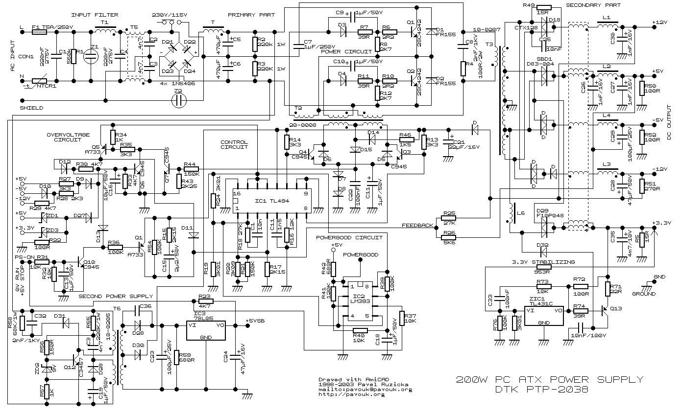
Does anyone have a detailed schematic for an AT Power Supply?

My intention is to intercept the DC output from the first stage,before it is converted to

high frequency,and insert a separate DC Source,in effect,eliminating the need for AC

input.

Thanks in advance for all help on this.

__________________
"A man never stands so tall as when he stoops to help a child." "Never argue with a stupid person.They will drag you down to their level and beat you with experience" "To create an apple pie from scratch, first you must create a universe"
Register to Reply
Interested in this topic? By joining CR4 you can "subscribe" to
this discussion and receive notification when new comments are added.

Good Answers:

These comments received enough positive votes to make them "good answers".

"Almost" Good Answers:

Check out these comments that don't yet have enough votes to be "official" good answers and, if you agree with them, vote them!
2
Guru

Join Date: Mar 2007
Location: by the beach in Florida
Posts: 33392
Good Answers: 1817
#1

Re: AT Power Supply Schematic

05/20/2015 2:14 PM
__________________
All living things seek to control their own destiny....this is the purpose of life
Register to Reply Good Answer (Score 2)
3
Power-User

Join Date: May 2010
Location: Cambridge, MA
Posts: 390
Good Answers: 82
#12
In reply to #1

Re: AT Power Supply Schematic

05/31/2015 7:35 AM

HiTekRedNek, You'll see that this supply schematic shows a bridge rectifier feeding high-voltage electrolytic capacitors. These are called "bulk" capacitors and have 300 to 350 volts across them, so that's the DC voltage you'd need.

One interesting thing: You don't necessarily need to go inside the circuit to connect an external DC supply. If you set the switch to the 230V position, you can simply power it from DC connected to the AC-line connectors!

Modern computer power supplies work differently. They no longer simply rectify the AC line into the bulk capacitors. That's because such rectification and capacitor charging occurs as high current spikes at the top of every AC-line cycle, which is very bad! Instead they use PFC, or Power-Factor-Correction circuitry. Yes, they usually have an input bridge rectifier, but it goes to a rather small storage capacitor (like 0.5uF), and immediately to a boost converter, to step-up and charge a larger bulk capacitor, which holds power throughout the AC cycle. The PFC is setup to draw a current from the AC line that's proportional to the instantaneous line voltage, as if the load was a resistor.

Depending on how the PFC circuitry is setup, you may be able to use the connect-DC-power-to-the-AC-line-plug trick as with the old designs. If you are willing to experiment, go for it, but be careful! Do it out on your driveway, there may be a fire!

One interesting consideration, you may be able to successfully use much lower DC voltages, perhaps as low as 100 to 120 volts. It'll also be happy working over a range of voltages, perhaps as low as 80 to as high as 350 volts. That's thanks to the boost converter aspect of PFC.

I see you now saying your available DC voltage is too low to apply to the bulk-capacitor node. But maybe it's high enough for the PFC input? If not, let me suggest that a simple boost converter from your available lowish DC voltage to say 120 volts DC out, is much more simple for you to make

(or even buy on eBay, see pic) than a full-fledged inverter, as some have suggested. BTW, this cheap eBay item is set for *)V max output, but it's easy to modify for higher voltages: change the output caps and feedback resistor. email me for a drawing.

__________________
Thanks, Win
Register to Reply Good Answer (Score 3)
3
Power-User

Join Date: May 2010
Location: Cambridge, MA
Posts: 390
Good Answers: 82
#13
In reply to #12

Re: AT Power Supply Schematic

05/31/2015 1:33 PM

I meant to write, 80V max. The PCB comes with 100-volt output caps installed, and the switching transistor, Q1, a SUP85N10, is rated at 100V.

This boost circuit was discussed in an earlier CR$ thread, Power-Supply-DC-DC-Step-Up-Converter-Problem, where, having bought one these eBay supplies, I reverse-engineered to get a drawing, and discussed its operation in several posts in the thread. You should start by reading those posts.

I modified one of these supplies for much higher voltages, using a single 100uF 250V output cap, replacing the MOSFET with a common IRF740 type, rated at 400V, and changing R10 from 3k to 2k, or lower. These simple changes worked fine, and allow you to boost to higher output voltages.

It's useful to understand the basic principles of boost-type switching converters, and pardon me for suggesting that Chapter 9 in our new book, The Art of Electronics, 3rd-edition, is a great place to learn about it. But you don't have to plunk down $93 to read it, because our publisher has offered it as a free sample chapter. Here's a DropBox link to Chapter 9, which you may freely share. Boost converters are discussed in 9.6.6, page 647 of the book, or page 71 of the file.

Anyway, we'd like to evaluate the power capability of this low-cost $12 eBay circuit, We can do this by calculating Iout. To do that we first need the ON duty cycle of the switch Q1, (E'qn 9.4d), which is D = 1 - Vin/Vout. For example, if our programmed loop-controlled output was 120 volts, and our input happened to be only 16 volts, then D = 1 - 16/120 = 0.867, or 87%. Looking at (E'qn 9.4a) we see Iout = Iin / (1-D), or Iout = 13% Iin, for our selected operating voltages.

I'm pretty sure the designer's intention was for you set to the (input) current limit to 10A. Under this condition, with Vin = 60V, the supply would work up to 600 watts, as advertised. But with only 16 volts in, we can only boost 160 watts max into our 120-volt output.

This means that even tho you hook our boost-converter's 120Vdc output to an ATX power supply, it'll only work properly up to about 150 watts of total load.

To go to higher power levels, you'd need to have higher input voltages, or need to run the MOSFET to higher maximum currents (choose a different type, like an FDP2710, or see Table 3.4b, page 189 in the book), and probably change the hand-wound toroidal inductor, L2, so it doesn't saturate.

__________________
Thanks, Win
Register to Reply Good Answer (Score 3)
Guru
United Kingdom - Member - Indeterminate Engineering Fields - Control Engineering - New Member

Join Date: Jan 2007
Location: In the bothy, 7 chains down the line from Dodman's Lane level crossing, in the nation formerly known as Great Britain. Kettle's on.
Posts: 32175
Good Answers: 839
#2

Re: AT Power Supply Schematic

05/20/2015 2:41 PM

The manufacturer does. It must surely be worth a phone call to find out.

__________________
"Did you get my e-mail?" - "The biggest problem in communication is the illusion that it has taken place" - George Bernard Shaw, 1856
Register to Reply
Guru
New Zealand - Member - Kiwi Popular Science - Weaponology - New Member Engineering Fields - Power Engineering - New Member Engineering Fields - Electrical Engineering - New Member

Join Date: Sep 2006
Location: Auckland, New Zealand
Posts: 8777
Good Answers: 376
#4
In reply to #2

Re: AT Power Supply Schematic

05/20/2015 3:51 PM

Hahahahahahahahahhaa.

Oh, were you serious?

__________________
jack of all trades
Register to Reply
Guru
New Zealand - Member - Kiwi Popular Science - Weaponology - New Member Engineering Fields - Power Engineering - New Member Engineering Fields - Electrical Engineering - New Member

Join Date: Sep 2006
Location: Auckland, New Zealand
Posts: 8777
Good Answers: 376
#3

Re: AT Power Supply Schematic

05/20/2015 3:48 PM

Why, they are not designed for this? They are designed for a single purpose and mass produced the heck out of to drive the price down.

Its probably possible but rather unlikely you will find the proprietary schematic to your power supply (manufacturers don't give these out), so expect to do some careful tracing using free generic schematics online as a bit of a guide.

__________________
jack of all trades
Register to Reply
Guru

Join Date: Dec 2010
Posts: 1895
Good Answers: 44
#5

Re: AT Power Supply Schematic

05/20/2015 3:59 PM

It would likely be easier to install a DC to DC converter, unless you want to retain the original power supply(?).

I am doing this for a few things in my motorhome to eliminate the unnecessary and wasted consumption (AC/DC/DC --> DC/DC).

Register to Reply
Guru

Join Date: Oct 2006
Location: 44.56024"N 15.307971E
Posts: 8277
Good Answers: 270
#8
In reply to #5

Re: AT Power Supply Schematic

05/20/2015 6:46 PM

True,it would be easier to buy a DC/DC converter,but I was trying to use what I had lying around in my scrap heap to save a few bucks.

Anyway,after looking at the generic schematic,I realize that the input DC voltage to the power section is far higher than I can provide,so I will just abandon the idea.

Thanks to everyone for all the feedback.

__________________
"A man never stands so tall as when he stoops to help a child." "Never argue with a stupid person.They will drag you down to their level and beat you with experience" "To create an apple pie from scratch, first you must create a universe"
Register to Reply
Guru

Join Date: Sep 2009
Posts: 1056
Good Answers: 88
#6

Re: AT Power Supply Schematic

05/20/2015 3:59 PM

Not much of a diagram needed. Locate the two big, series connected electrolytic capacitors, rated about 200V. Get rid of rectifier bridge, 120V/240V switch and any PF correction circuits and connect your DC voltage to those electrolytics. If you don't know exactly where to connect the voltage, forget the whole project, it's obviously too dangerous for you and schematic won't help much. ALSO, your DC voltage MUST be between 300V and 360V, current limited at the time of the connection. If you have different voltages available, mods could be made, but then generic schematics are also useless, since not all AP supplies are created equal and experience on switching supplies is essential. And don't forget for a second, those voltages are lethal. S.M.

__________________
Life is complex. It has a real part and an imaginary part.
Register to Reply
Guru

Join Date: Dec 2008
Location: Cd. Juarez, Chihuahua, Mexico.
Posts: 1023
Good Answers: 69
#7

Re: AT Power Supply Schematic

05/20/2015 4:41 PM

That first stage is just the incoming voltage rectified, passed thru a reactor and filtered with two 470uF Caps. You can build it yourself, don't need to take apart a power supply.

__________________
No hay conocimiento ni herramienta que sustituya al sentido comun.
Register to Reply
Guru
Popular Science - Weaponology - New Member Safety - ESD - New Member Hobbies - Fishing - New Member

Join Date: Sep 2006
Location: Near Frankfurt am Main, Germany. 50.390866N, 8.884827E
Posts: 17996
Good Answers: 200
#9

Re: AT Power Supply Schematic

05/21/2015 1:01 PM

You did not tell us why, but I assume you wanted to go mobile, or maybe use solar energy?

A laptop would be easier to use, plenty of low voltage power supplies, 12 or 24 volt nominal.... but if you are set on a PC, then simply use a mains converter and the original power supply as it is....

__________________
"What others say about you reveals more about them, than it does you." Anon.
Register to Reply
Anonymous Poster #1
#10

Re: AT Power Supply Schematic

05/21/2015 1:06 PM

There are some good breakdowns of computer supplies/alternate uses on 'instructables.com', browse around a bit.

Register to Reply
Guru
Engineering Fields - Power Engineering - New Member

Join Date: May 2007
Location: NYC metropolitan area.
Posts: 3230
Good Answers: 444
#11

Re: AT Power Supply Schematic

05/21/2015 6:49 PM

If you're hellbent on using 12 volts to run a desktop and you happen to have a spare UPS that you can cannibalize, then simply remove the old batteries from it and run some number 10 wires from your batteries to the battery connections inside the UPS. The only caveat is the DC input voltage, some UPS use 12V, others connect two 12V batteries in series for 24V, you'll have to look at how the old batteries are wired together.

One thing you don't want to do is plug the UPS into the AC supply unless all the leads and terminals are fully insulated since some UPS have one side of the line connected to the batteries through the charging circuitry. It's also possible that the built-in charging circuit won't "like" the charging current that an automobile battery can draw and will indicate a fault, shutdown, and/or refuse to charge it, but standalone operation should be no problem.

__________________
“Tell me and I forget. Teach me and I remember. Involve me and I learn.” Ben Franklin.
Register to Reply Score 1 for Good Answer
Register to Reply 13 comments

Good Answers:

These comments received enough positive votes to make them "good answers".

"Almost" Good Answers:

Check out these comments that don't yet have enough votes to be "official" good answers and, if you agree with them, vote them!
Copy to Clipboard

Users who posted comments:

Andy Germany (1); Anonymous Poster (1); cuba_pete (1); HiTekRedNek (1); jack of all trades (2); PWSlack (1); RAMConsult (1); SimpleMind (1); SolarEagle (1); Winfield Hill (2); Yahlasit (1)

Previous in Forum: Hazardous Area Classification   Next in Forum: A Question About Lighting Design in Accordance With EN 12464-1

Advertisement