Previous in Forum: Instrumentation - Current Generator not Generating Voltage   Next in Forum: DP TRANSMITTER ABOVE TAPS
Close
Close
Close
12 comments
Associate

Join Date: Aug 2010
Location: India
Posts: 32

How to Select the Pressure Gauge Type

08/13/2010 3:32 AM

Sorry to ask a basic question,also may be already asked in this site. Still want to discuss.

My problem is how to select which type of Pressure Gauge is to selected, range-wise

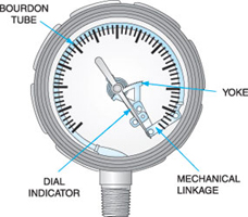
I am aware of all kind of principles involved and there use viz., Bellow, Diaphragm, Borden, (sub category: Seal type, differential, relay, schaffer, etc.).

Still: Is there some specific range for them --

like for 0-1 bar Diaphragm should be used ,

for low ranges Pressure Gauge (mmWC type ) ,

for high pressure Bellow type ?

Please Guide me with your experience.

__________________
“Reality leaves a lot to the imagination.”
Register to Reply
Interested in this topic? By joining CR4 you can "subscribe" to
this discussion and receive notification when new comments are added.

Comments rated to be "almost" Good Answers:

Check out these comments that don't yet have enough votes to be "official" good answers and, if you agree with them, rate them!
Guru
United Kingdom - Member - Indeterminate Engineering Fields - Control Engineering - New Member

Join Date: Jan 2007
Location: In the bothy, 7 chains down the line from Dodman's Lane level crossing, in the nation formerly known as Great Britain. Kettle's on.
Posts: 32049
Good Answers: 838
#1

Re: How to Select the Pressure Gauge Type

08/13/2010 8:11 AM

No, there isn't a specific range criterion, though there are application differences.

One wouldn't use a diaphragm gauge on steam, for example, though one would be using a pigtail loop to provide a buffer of water between the gauge and the service line, wherever possible.

The diaphragm is there to prevent any chemistry getting into the mechanism and the two interacting. Diaphragms vary in their wetted materials; PTFE-coating is one way of protecting the gauge and the process from each other.

__________________
"Did you get my e-mail?" - "The biggest problem in communication is the illusion that it has taken place" - George Bernard Shaw, 1856
Register to Reply
Associate

Join Date: Aug 2010
Location: India
Posts: 32
#6
In reply to #1

Re: How to Select the Pressure Gauge Type

08/14/2010 2:01 AM

Thanks buddy,

Yes that is what exactly i wanted. i work in water and waste water industry, Pressure hardly varies from 0.6 - 40 Kg . in Sewage, Air Blower line , water line etc.,.

i wish if you can suggest more on this as per your experience Application wise,

where to put bellow and where we cant;

I am not taking about range selection of a PG,

__________________
“Reality leaves a lot to the imagination.”
Register to Reply
Associate

Join Date: Jul 2008
Location: India, Kuwait
Posts: 31
#7
In reply to #6

Re: How to Select the Pressure Gauge Type

08/14/2010 5:06 AM

I would suggest you opt for a bourdon type gauge with a diaphragm seal so that you can prevent any waste material entering the bourdon. Preferable material would be SS316 with a blow out protection at the back.

Register to Reply
Guru
United Kingdom - Member - Indeterminate Engineering Fields - Control Engineering - New Member

Join Date: Jan 2007
Location: In the bothy, 7 chains down the line from Dodman's Lane level crossing, in the nation formerly known as Great Britain. Kettle's on.
Posts: 32049
Good Answers: 838
#11
In reply to #6

Re: How to Select the Pressure Gauge Type

01/20/2025 10:42 AM

The <...water and waste water industry...> has standards that must be followed. Ask there.

__________________
"Did you get my e-mail?" - "The biggest problem in communication is the illusion that it has taken place" - George Bernard Shaw, 1856
Register to Reply
Anonymous Poster
#2

Re: How to Select the Pressure Gauge Type

08/13/2010 11:26 AM

Choose a gage that the full scale pressure is about twice the anticipated pressure that needs to be measured. This is the most accurate portion of the gage and will allow for some unexpected pressure increase.

Register to Reply
Guru
United Kingdom - Member - Indeterminate Engineering Fields - Control Engineering - New Member

Join Date: Jan 2007
Location: In the bothy, 7 chains down the line from Dodman's Lane level crossing, in the nation formerly known as Great Britain. Kettle's on.
Posts: 32049
Good Answers: 838
#10
In reply to #2

Re: How to Select the Pressure Gauge Type

08/15/2010 8:12 AM

Safety relief valves, pressure trip systems and blow-out panels/discs are there to provide for unexpected pressure increases!

__________________
"Did you get my e-mail?" - "The biggest problem in communication is the illusion that it has taken place" - George Bernard Shaw, 1856
Register to Reply
Associate
Pakistan - Member - New Member

Join Date: Dec 2009
Posts: 29
#3

Re: How to Select the Pressure Gauge Type

08/13/2010 1:20 PM

Dear All,

Please Note,

Measuring Pressure

Matching the Fluid and Application

Units of Measure

Sub-atmospheric pressures are measured in several units, including: Torr (also called millimeters of mercury, mmHg), milliTorr (mTorr but also called micron, μ), inches of mercury (" Hg), millibar (mbar), and pascal (Pa). In the U.S., three units are in common use: micron as the unit for pressures reached by backing pumps, Torr for high vacuum and UHV pumps, and inches of mercury for coarse vacuum pumps. In Europe, millibar is the common unit for all pressure measurements. Japan uses the pascal unit, but often has Torr as a secondary unit. Most authors of scientific/technical papers are urged to use the SI unit pascal, and some do.

The units are derived from:

  • Pascal—the force of 1 newton (1 kg accelerating at 1m/sec./sec.) acting on 1 m2
  • Millibar—1,000 times the force of 1 dyne (1g accelerating at 1cm/sec./sec.) acting on 1 cm2
  • Torr—1/760 times the height of a mercury barometer under "standard" atmospheric pressure
  • MilliTorr or micron—1,000th of 1 Torr
  • Inches of Hg (vacuum)—1/29.92 times the height of a mercury barometer under "standard" atmospheric pressure (taking atmospheric pressure as 0" Hg)
  • Inches of Hg (weather forecasts)—1/29.92 times the height of a mercury barometer under "standard" atmospheric pressure (taking no pressure as 0" Hg)


Pressure Ranges

There is no "universal" gauge that can measure from atmosphere to UHV pressures (a dynamic range of 1015). There are, essentially, three mechanisms used in pressure measurement and the one chosen depends on the pressure range and the residual gases in the vacuum.

Pressure Range

Mechanical Gauges have liquid or solid diaphragms that change position under the force of all the gas molecules bouncing off them. These gauges measure absolute pressures unaffected by gas/vapor properties. Unfortunately, this type of gauge is ineffective below 10-5 Torr.

Gas Property Gauges measure a bulk property, such as thermal conductivity or viscosity. They are dependent on gas composition and are effective over limited pressure ranges below approximately 100 Torr and above 10-4 Torr.

Ionization Gauges For high vacuum and UHV measurements, charge collection is used. The residual gas molecules are ionized by electrons and the resulting ion current measured. Although such gauges will ionize vapors as well as permanent gases, their response depends on parameters other than ionization potential, making accurate total pressure measurement difficult in gas mixtures. Ionization gauges cover the pressure range from 10-4 Torr to 10-10 Torr.

The typical arrangement of two gauges covering the range of interest between 10 and 1 x 10⁹ Torr leaves a poorly covered band at pressures widely used in sputtering, etching, CVD, etc. Fortunately, the precise measurements needed between 10-1 and 10-3 Torr for reproducible processing can be made by adding a third gauge—the capacitance manometer.

When choosing a gauge, in addition to pressure range, other features should be considered: the gauge's pumping speed; how it is affected by radiation, magnetism, temperature, vibration, and corrosive gases; and the damage caused by switching it on at atmospheric pressure. These subjects are discussed in comprehensive vacuum texts such as John F. O'Hanlon's A User's Guide to Vacuum Technology.

Vacuum Gauges

Mechanical Gauges

A gas's pressure is the sum of all the individual forces caused by each atom or molecule colliding with a surface at any instant. Mechanical gauges register this total force by monitoring the surface's movement against the (restoring) force trying to keep the surface in its original place. Because mechanical gauges respond to molecular momentum only, they measure pressures of any gas or vapor. They can be very accurate or inaccurate depending on how the movement is registered.


McLeod

This gauge, though seldom used, is employed mostly as a primary calibration standard for other gauges. In effect, a large known volume of gas at unknown pressure is captured in a glass bulb and compressed by raising the mercury level until the gas is confined in a small, closed capillary of known volume. Because the ratio between the original and final volumes is known and the final pressure can be measured, the original pressure is calculated by Boyle's law (P1 x V1 = P2 x V2). McLeod gauges are particularly useful in the 1 Torr to 10-4 Torr range but, because of the compression, cannot be used to measure vapors.


Bourdon

Bourdon


When a closed-end, curved, oval cross-section, copper alloy tube is connected to the vacuum, atmospheric pressure bends it to a greater or lesser degree, depending on the internal pressure. The mechanical force moves an indicator needle through a geared linkage. Bourdon gauges are used primarily in high-pressure measurement (most commonly attached to regulators on gas cylinders), but variations are built to indicate pressures from 0" Hg to 30" Hg and are used for freeze drying, "house" vacuum systems, vacuum impregnation, etc., where the major concern is whether vacuum exists rather than its accurate measurement.

Piezo

Piezo-resistive pressure sensors are typically comprised of a silicon wafer that is machined on a surface that makes the crystal into a suitable deflecting diaphragm when subjected to a normal stress (pressure). The thickness of the silicon crystal at its minimum section is the primary factor that determines the pressure range of the gauge from 1,500 to 0.1 Torr. As the diaphragm deflects under pressure, the resistances of the piezo-resistive elements change in value, causing the Wheatstone bridge network to move out of balance. Applying a voltage to this bridge produces an output voltage that is proportional to the applied pressure. If the elements are of equal resistance, there will be a zero output voltage with no pressure differential across the diaphragm.


Capacitance Manometers

Manometer

The deflection of a thin metal diaphragm separating a known pressure from an unknown pressure is a measure of the pressure difference between the two volumes. In the capacitance manometer, as the name suggests, the deflection is measured using the electrical capacitance between the diaphragm and some fixed electrodes. Capacitance manometers are the most accurate devices for measuring the differential or absolute pressure of all gases (including vapors that do not condense at the gauge's operating temperature).

Gauge heads are specified by their maximum measured pressure (25,000 Torr down to 1 x 10⁻¹ Torr), with each head having a dynamic range of approximately 104 below that. Accuracies of 0.25% gauge reading are common, with 0.08% available from high-accuracy products.

All types of pressure gauges are affected by ambient temperature changes, but other error sources are so much larger that emperature is ignored. The capacitance manometer, by contrast, is so accurate that gauge-head temperature variation is a critical source of error. We strongly suggest that capacitance manometers be purchased only from reputable manufacturers who understand sources of error and demonstrate effective ways of counteracting them.


Diaphragm Manometers

Like the capacitance manometer, these gauges use the deflection of a thin metal (or silicon) diaphragm separating a known pressure from an unknown pressure. However, in this type of gauge, the deflection is sensed by a strain gauge attached to the diaphragm. While this limits the minimum measurable pressure to 1 Torr, it does provide a stable, repeatable, device reading pressures up to 1,200 Torr.


Gas Property Gauges

The thermal conductivity or viscosity value for each specific gas is different and varies non-linearly with pressure. Gas property gauges, presented with the typical vacuum chamber gases, are inaccurate. This, and numerous other inherent error sources, suggest the gauge readings are acceptable for noting repeating pressure events but of little use in measuring absolute pressures.


Thermocouple


Thermocouple (T/C)

The pressure range between 10 Torr and 10-3 Torr is indicated by measuring the voltage of a thermocouple spot-welded to a heated filament exposed to system gas. The filament, fed from a constant current supply, reaches a temperature determined by the amount of energy extracted by the gas. At higher pressures, more molecules hit the filament and extract more energy than at low temperatures. The filament temperatures induce thermocouple voltage changes. These gauges are used extensively in foreline monitoring and to provide the signal to automatically switch the main chamber from backing and high-vacuum pumps at the crossover pressure.

Pirani

Pirani

In a Pirani gauge, two filaments, often platinum, are used as two arms of a Wheatstone bridge. The reference filament is immersed in a fixed-gas pressure, while the measurement filament is exposed to the system gas. Both filaments are heated by the current through the bridge but, unlike most T/Cs, the Pirani gauge does not use constant voltage or power, but constant filament temperature. Gas molecules hitting the immersed element conduct energy away that is detected and replaced by the feedback circuit to the power supply. This variation of mechanism gives the Pirani gauge perhaps 100 times longer total pressure range (although the same dynamic range for each sensor head) and a faster response. The Pirani gauge is used in the same applications as the T/C gauge. Although the dynamic range for any single gauge matches the T/C, Pirani's cover a pressure range from about 10 Torr to 1 x 10⁻⁵ Torr.


Convection


Convection

This gauge's mechanism differs from that used in the T/C and Pirani gauges only by using a structure that enables the natural convection in (viscous flow) gases to aid in removing heat from the hot filament. Convection gauges measure pressures over the range from about 10 Torr to atmosphere.

Ionization Gauges

With relatively minor differences, all ionization gauges use the same principle. Energetic electrons ionize the residual gases—the positive ions are collected at an electrode and the current is converted to a pressure indication. Hot filament gauges (Bayard-Alpert, Schulz-Phelps) use thermionic emission of electrons from a hot wire, while cold cathode gauges (Penning, Inverted Magnetron) use electrons from a glow discharge or plasma.

All ion-gauge measurements are seriously affected by gas composition. For example, a report in J. Vac. Sci. Tech. indicates an ion gauge's relative sensitivity (relative to N2 = 1) is 5 for acetone vapor and 0.18 for He. That is, the same absolute pressure of these pure (gaseous) materials will give a gauge indication differing by a factor of almost 28. Ionization gauges do not give accurate absolute pressure measurements unless recently calibrated with the exact gas mixture that is to be measured.

Sensitivity

The term relative sensitivity used above should not be confused with the parameter called the 'gauge sensitivity.' The latter comes from the equation relating the gauge's positive ion current (ip) for a given electron emission (ie) at given gas pressure (P): ip = S x ie x P or P = 1/S x ip/ie

The constant of proportionality (S in units of reciprocal pressure) is the 'gauge sensitivity.' Practical (hot filament) ion gauges have gauge sensitivities ranging from 0.6 Torr-1 to 20 Torr-1. This is important when selecting an ion gauge controller because the gauge's sensitivity must be within the controller's available range.


Hot Filament Gauges

Ion


The two common hot filament ion gauges, Bayard/Alpert (B-A) and Schulz-Phelps (S-P), differ only in the physical size and spacing of their electrodes. Both have heated filaments biased to give thermionic electrons of 70eV, energetic enough to ionize any residual gas molecules with which they collide. The positive ions formed move to an ion collector held at -150V. The current varies with the gas number density (the number of molecules in each cc), which is a direct measure of gas pressure.

Bayard-Alpert ion gauges have a reasonably linear response from 1 x 10⁻⁴ Torr to 1 x 10⁻⁹ Torr, with gauge sensitivities from 5 to 20 Torr-1. B-A gauges are available with one or two filaments (the second acting as a spare) and with two filament materials thoria-coated iridium, used in oxygen-rich applications and for 'burn-out' protection if accidentally vented and tungsten, used for lower cost and in residual gases containing halogens.

The standard B-A gauge measures down to 1 x 10⁻⁹ Torr. It does not go lower because primary electrons generate soft X-rays when they hit the grid. An X-ray hitting the ion collector electrode releases a photoelectron, which is indistinguishable from positive ions arriving there. Below 1 x 10⁻⁹ Torr, photoelectron emission is a large enough fraction of the ion current to distort the pressure reading. Special B-A structures with ultra-thin ion collectors will reach 10-10 Torr and perhaps even into the 10-11 Torr range.

Cold Cathode Gauges

ColdCathode

In the CCGs the ionizing electrons are part of a self-sustaining discharge. However, since the CCG has no (thermionic emission) filament, the discharge is initiated by stray field emission or external events (cosmic rays or radioactive decay). At low pressures, this can take minutes and CCGs are usually switched on at high pressure. Once started, the gauge's magnetic field constrain the electrons in helical paths, giving them long path lengths and a high probability of ionizing the residual gas. The ions are collected and measured to determine the gas pressure.

Many electrode geometries have been used—cylinders, plates, rings, rods, in various combinations with the magnetic field direction and strength chosen to maximize the measured current. If the gauge's central or 'end' electrodes are negative, the convention is to call this a magnetron. If the same electrodes are positive, the gauge is called an inverted magnetron.

Magnetron: The initial Penning design (cylindrical anode and end plate cathodes) was neither precise nor accurate and it was replaced by other geometries. However, the name Penning is still used even for magnetrons with central wire or ring cathodes. The operating voltage is limited (typically to ~2kV) to avoid field emission effects that cause increases in the ion current unrelated to pressure. While the newer magnetron designs are satisfactory, they are limited to the top of the high vacuum range and attract little commercial attention.

Inverted Magnetron: Largely due to the development efforts of Redhead and his colleagues, this design works into the UHV pressure range. Its axial central anode enters the cylinder/end plates cathode through voltage guard rings (to prevent field emission affecting the ion current measurement). The anode carries a much higher potential than the normal magnetron (~6kV) and is parallel to the gauge's magnetic field. Some commercially available inverted magnetron designs have good linearity and operating characteristics down to 1 x 10-11 Torr. However, attempting to start one at such low pressures may take hours or days.

Residual Gas Analyzers

Special mass spectrometers designed to analyze gases remaining in a vacuum chamber are called residual gas analyzers or RGAs. The wealth of information about experimental or process conditions offered by an RGA makes a permanently attached unit a convenient, often necessary, diagnostic device.

Quadrupole RGAs, named for the four rods used in the mass filter section, are powered by mixed RF/DC voltages. Full operating details are beyond this text but are dealt with adequately in many books, such as Dawson's Quadrupole Mass Spectrometry And Its Applications and the AVS's monograph by Drinkwine, et al, Partial Pressure Analyzers and Analysis. The quadrupole analyzer (or sensor head) bolts to the vacuum system. It consists of an ionizer (ion source) connected to the mass filter, which in turn is attached to an ion detector, all mounted on a UHV flange (often a 2-3⁄4" O.D. CF) carrying the feedthroughs for power and signals. The combined RF/DC voltage is generated close to the sensor head. From here, only main power voltage and returning signal information connect to the control chassis and display or desktop PC. In the ionizer, neutral gas atoms and molecules are bombarded with 70eV electrons from a hot filament. The ionized species are extracted into the quadrupole, where only those ions with the appropriate mass-to-charge (m/e) ratio for the applied RF/DC voltages are transmitted. By varying the RF/DC voltage with time, the m/e ratios are scanned and the ion current at each mass is recorded as a spectrum.

Diagnosing vacuum problems with an RGA requires only a collection of fragmentation patterns from which the following may be quickly determined: the presence of air and water leaks; unacceptable levels of active gases such as O2, H2, and H2O, pump oil backstreaming, the presence of Fl or Cl compounds; the regeneration requirements of a cryopump, and the purity of backfill gases. Because an RGA operates at or below 10-4 Torr, high-pressure processes are analyzed with the RGA installed in an auxiliary vacuum system, often a mobile cart moved to various vacuum stations.

Leak Detectors

Leak detectors are mass spectrometers that detect only helium ions at m/e = 4. Because they are specific, they detect extremely small concentrations of helium in the presence of large quantities of other gases. As the name implies, these devices determine the presence of leaks and help locate them. Excellent leak detection instructions are available in Harris' book, Modern Vacuum Practice or available as part of our Lesker University curriculum.

The chamber under test and the leak detector are connected via a vacuum-tight tube and the chamber is evacuated using the leak detector's own vacuum system. Helium is sprayed from a fine nozzle at the chamber's surface where it displaces the air diffusing through the leak only while the probe is directed at the leak's position. It is a common misconception that the pressure in the chamber must be low before leak testing can start. In fact, chamber pressures lower than 10-2 Torr are rarely needed. Once the leak detector inlet valve is fully open, further efforts to reduce pressure in the chamber only waste time. During one operator's 11-year leak-checking experience, for example, most leaks were detected while the leak detector's inlet valve was only partially cracked. Leaks larger than 1 x 10⁻⁵ atm cc/sec. are the most common—"some" leaks were in the 1 x 10⁻⁶ atm cc/sec. range, six leaks were in the 1 x 10⁻⁷ atm cc/sec. range, two in the 1 x 10⁻⁸ atm cc/sec. range, and only one in the 1 x 10⁻⁹ atm cc/sec range. Because most leak detectors have a minimum detectable leak rate of 1 x 10⁻¹⁰ atm cc/sec., detection sensitivity is rarely a problem for locating real leaks

Regard's

AUR

__________________
AUR
Register to Reply Off Topic (Score 4)
Guru
Safety - Hazmat - New Member Engineering Fields - Retired Engineers / Mentors - New Member Engineering Fields - Piping Design Engineering - New Member Hobbies - DIY Welding - New Member Fans of Old Computers - PDP 11 - New Member

Join Date: Feb 2007
Location: Stronger Than The Storm
Posts: 2394
Good Answers: 203
#4

Re: How to Select the Pressure Gauge Type

08/13/2010 11:53 PM

RANGE-

range selection is usually done in so that the normal operating range is within the middle 1/3 of the scale. i.e. for a 40-60 psi operating range you would select a 1-100psi guage, 400-500 psi op range would use a 1,000psi guage.

__________________
Any day on the green side of the grass is a GREAT DAY!, --- me +++++++++. I believe creativity is an inherent part of everyone. --- Kermit T. Frog
Register to Reply
Associate

Join Date: Aug 2010
Location: India
Posts: 32
#5
In reply to #4

Re: How to Select the Pressure Gauge Type

08/14/2010 1:54 AM

Thanks for replying , however my worry is not the scale rather selection of

Diaphragm, Bourden , Bellow .

Like friend PWSLACK stated that one wouldn't use a diaphragm gauge on steam ,

(why cause SS316 element hasn't that much of capacity or diaphragm is there to prevent any chemistry getting into the mechanism and the two interacting ) .

I am not asking about the parameters like Seal, PTFE , diffrential , Gylecrine filled .

__________________
“Reality leaves a lot to the imagination.”
Register to Reply
Guru
United Kingdom - Member - Indeterminate Engineering Fields - Control Engineering - New Member

Join Date: Jan 2007
Location: In the bothy, 7 chains down the line from Dodman's Lane level crossing, in the nation formerly known as Great Britain. Kettle's on.
Posts: 32049
Good Answers: 838
#12
In reply to #5

Re: How to Select the Pressure Gauge Type

01/20/2025 10:43 AM

<...not asking about the parameters like Seal, PTFE , diffrential , Gylecrine filled...>

So, what is the question?

__________________
"Did you get my e-mail?" - "The biggest problem in communication is the illusion that it has taken place" - George Bernard Shaw, 1856
Register to Reply
Power-User

Join Date: Nov 2009
Posts: 334
Good Answers: 63
#8

Re: How to Select the Pressure Gauge Type

08/14/2010 12:26 PM

Usually, the choice of pressure elements comes down to what is available in the pressure range and materials of construction needed for a given installation.

Does anyone make a hastalloy bourdon tube for 5"H2O? I doubt it. Not that it couldn't be manufacturered, but the cost would be too high to support its design and manufacture.

The manufacturers make decisions about what to sells well enough in a given market category to warrant manufacturing, as described in Ametek US Gauge's 1985 Pressure Gauge Handbook:

3.9 CHOOSING THE MEASURING ELEMENT

It will be apparent from the foregoing discussion that a variety of pressure elements is available to the gauge designer. The choice depends primarily on the required performance and secondarily on the cost. Where either of two elements will meet the performance requirements, including accuracy and reliability, then the least costly would be the usual choice.

For pressure measurement above 100 psi, some form of the bourdon is normally selected (i.e., C shape, helical, or spiral). Bourdons may be used to give a 2700 pointer rotation for ranges as low as 12 psi and are less costly than the other types of elements.

For lower pressure, the diaphragm or bellows element is used, and for very low pressure a slack diaphragm is required. Metallic diaphragms can be formed of materials that do not lend themselves to metallic bellows- One important example is the use of Ni-Span C for diaphragm elements. Also, diaphragm elements can be made with a motion that is nonlinear with pressure (i.e., linear with altitude, air speed, flow), whereas formed bellows almost always have a linear-with-pressure characteristic. Bellows elements generally exhibit a much larger volume change with pressure than do diaphragm elements or bourdons. This may he important where a high response rate is desired or where the gauge is used in conjunction with a diaphragm seal.
-- end --

Or they sum up some of the features if various sensor elements, as Wika does:

Wika Handbook (US Edition), 1998:

Compared to diaphragm and capsule type measuring elements, Bourdon tubes have the following advantages:
- They cover pressure ranges from just 0/10 PSI up to very high pressure ranges of 0/150,000 PSI.
- They have a large, measurable tip travel that is linear.
- They have accuracies up to ASME Grade 4A (±0.1% of span).

1.4.1.2 Diaphragm measuring elements
Diaphragm measuring elements such as flat diaphragms and capsules are commonly used for low pressures from 0/0.5 "H2O up to around 0/400 PSI. A typical application is liquid level measurement in open tanks.

Due to their shape and position, diaphragms have high mechanical resistance and are less shocksensitive. They are commonly made of steel or 300-series stainless steel. For aggressive fluids, special corrosion-resistant materials such as tantalum, titanium, Hastelloy etc. are used, or the materials are coated with PTFE or similar materials. Open flanged connections are used if the process fluid is highly viscous, crystallizes or is contaminated.

Capsules
A capsule consists of two diaphragms that are welded or soldered together around their outer edge. The center of just one capsule half is supported in the case so that both halves can move freely. This design doubles the displacement of the diaphragm, allowing smaller pressures to be measured without any reduction of the wall thickness.

Capsule elements are currently being used for the measurement of flowing gases, i.e. in chambers or fans.

Even micropressures in the range of 0 to 0.5"H2O can be measured. The necessary displacement is accomplished by connecting several capsules in series (Figure 1.82). Evacuated capsules are used as measuring elements for aneroid barometers in the measurement of atmospheric air pressure.

1.4.1.3 Bellows
Bellows are used where a large displacement is required in a restricted space. Bellows are thinwalled cylindrical containers with deep corrugations in their periphery. When pressure is applied, the length of the bellows changes. Depending on the application, a supporting spring can be installed inside the bellows. Bellows are notable for their good linearity. Generally they are used in the range from 0 to 2.5 "H2O and 0 to 10 PSI.

The Wika Handbook is available electronically in .pdf.

http://www.wika.us/upload/BR_RF_Handbook_en_us_18447.pdf

Register to Reply Score 1 for Good Answer
Anonymous Poster
#9

Re: How to Select the Pressure Gauge Type

08/14/2010 10:36 PM

You can use bourdon type of pressure gauge for high pressure,if your process a chemical you can use Diaphragm flange type.water/ gas etc you can direct instal to the process.I think bellow only for low pressure measurement.about range you can calculate example process 1 kg/cm2 or 1 bar,use PG range 150% X max range

Register to Reply
Register to Reply 12 comments
Interested in this topic? By joining CR4 you can "subscribe" to
this discussion and receive notification when new comments are added.

Comments rated to be "almost" Good Answers:

Check out these comments that don't yet have enough votes to be "official" good answers and, if you agree with them, rate them!
Copy to Clipboard

Users who posted comments:

adeebulrehman (1); Anonymous Poster (2); Carl_E (1); gkishorenair (1); old salt (1); omsumitam (2); PWSlack (4)

Previous in Forum: Instrumentation - Current Generator not Generating Voltage   Next in Forum: DP TRANSMITTER ABOVE TAPS
You might be interested in: Pressure Gauges, Pressure Sensors, Pressure Switches

Advertisement