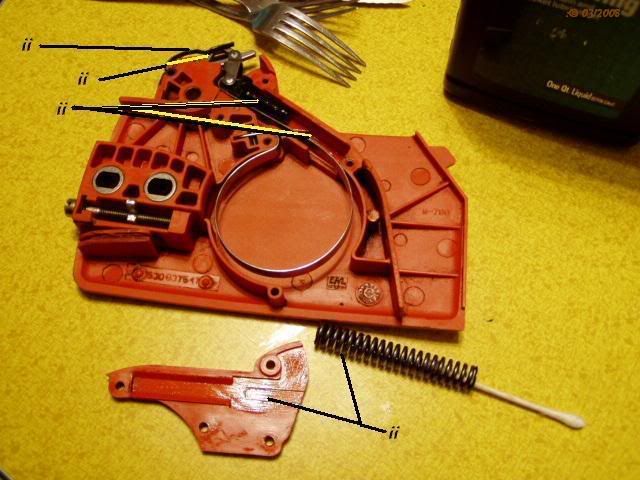
Hello members. This might take several picture postings, so...first pic first. Depicted below is the combination chain-(drive-clutch)-brake/anti-kickback mechanism assembly used on Husquvarna 36, 41 and similar felling-type (as opposed to arborist's') saws. I am hoping this question finds someone who has "been-there-done-that" when it comes to servicing (disassembling, resetting, reassembling) these (specifically, Husqvarna) assemblies; or one of those rare "mechanically minded's" able to "see through" a mechanism's cover; envision what goes on to accomplish the intended (system) function; and "see" how everything goes together according as designed. What you see here is the "Unit" in its assembled condition; however it is not assembled correctly--one interior component at least is out of place, with the result that:
- The Unit assy cannot be properly (if at all) fitted back (with binder band) over the chain drive clutch, and attached (along with bar and pictured chain) to the main saw body.
- The almost new (about 45-60 min. of use) saw cannot be used.
Now some background and a description of what is the problem. (Continued below picture)

Due to a possible design and/or mfg assembly flaw (or incorrect maintenance instructions in the user's manual could have played a part), when the saw was being operated something happened inside the assy (inside the handle and adjacent cover plate)--some kind of false triggering, slippage, misalignment, ...whatever--which resulted in the binder's (the circular strap's) being retracted to the "brake-on" position. (Presently, the binder is in extended, brake-off configuration; but, as said, the unit is incorrectly assembled...such that the anti-kickback mechanism is not set under tension. (That is to say, the handle should be pivoted fully rearward (not forward as shown) for the binder strap to be opened as shown.)
Now, with the binder strap in the retracted or near-retracted (applied or near-applied) state, the following functional faults come into play:
- When installed on the saw, the saw can be started but cannot be rev'ed to cutting (top rpm) speed; the centrifugal clutch mechanism that turns with the main drive shaft engages a clutch drum which in turn (being gripped by the binder strap) resists acceleration (increasingly with application of engine torque)...causing the chain, and engine, to stall—just as if the brake had been normally, manually applied to stop and idle the chain—or just as if a kickback had done the same.
- When not installed, the retracted binder cannot be fit over the clutch drum...hence the saw cannot be assembled for use.
- If affixed to the saw body (somehow), the unit assembly cannot be detached from the saw (as for normal maintenance service) since the drum will be in the grip of the binder strap; and forcing it off will cause damage.
So what is the problem? The next pic is the blow-up illustration of the chain brake handle assembly from the saw owner's manual.

Below is a better view of the upper rendering, showing the components of the anti-kickback/binder-self-triggering components more clearly. (Unfortunately, due to a poor explosion rendering, neither drawing reasonably depicts how the parts fit together when assembled.) (Continued under pic)

It is the multi-form, multi-directional spring (find 1, pn 530 01 59-01) which, in particular, is causing the problem with reassembly. It seems certain that it must project from a point of pivot (apparently the same as the handle pivot) upward and leftward (ala the drawing) into the the handle support part of the handle assy. However, the drawing does not depict how, and where, the spring (the spring's bitter end at right) engages with the binder-actuation link (pn 501 87 53-01). It is this interface between handle and link which seems to be critical to correct operation (and operability) of the anti-kickback and clutch/de-clutch functioning....
Below is a paste-up illustration showing the approximate orientation of components which ought to have been shown in the mfr's blow-up drawing.

This view shows the link assembly aligned just above its installed position with nipple at right fitted into groove on cover assy at bottom. The subject spring is shown, orphaned. In the pic below can be seen the interfaces (among others) between handle and pivot point on cover assy, and between link assy and link pivot point on handle. (Continued below pic.)

Finally, a few "real life" images to better show how the drawings relate to the actual assemblies.


Pics just above and below are reverse direction from previous subassembly dwg's.

Thank you for your help. And another thing, neither the owner manual nor the manufacturer/seller/or "authorized" service are of any help or use with this problem. The Husqvarna manuals are distinguishable only by the carelessness of their writing and editing (I even rewrote a Husky manual maintenance procedure which could never be done as written--my offer to provide it to the mfr fell on deaf ears. Similarly, this problem with the Husqvarna chain brakes appears to be "over the heads" of Husqvarna U.S. technical support.
Note: some of the illustration were composed using copies on transparencies of the manual depiction. However, I've not been able, due to inherent photocopier distortion, to make a superimposition "mock up" which might give a clue as to where the spring should fit in the overall assembly.

 2
2

 Re: Husqvarna's built-in chain brake problem-repair how-to


Good Answers:
"Almost" Good Answers: